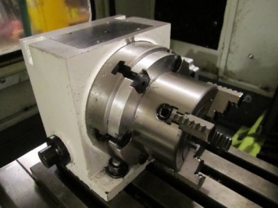
Some Ideas for Ease of Use

The thing about the rotary table that puzzles me is that I wrote down both decimal inches, and mm, and it doesn't strictly match anything.
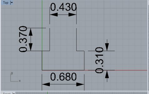
Tee-Slot.jpg

The width of the slot is 11.0 mm, the bottom width is 17.3mm, wide section height is 7.64mm and the narrow section height is 9.4mm.

The dimensions look like a 3/8 slot except for the width of the bottom part (0.68). Engineers' references say that should be bigger: 0.719 at minimum. In metric, that slot with of 11 mm is halfway between M8 and M10 at 10 and 12mm, respectively. Otherwise it looks like it would be M8, like you say. Either way, one dimension messes up the match.
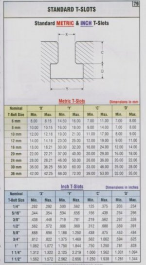
StandardTeeSlots.jpg
The slot is just a bit tight on 7/16 (.438) which is what I have for the 0704. I can slide one of those nuts in the slot if the nut's upside down, but the bottom slot is too narrow and the bottom section height is too short for the 7/16 Tee-nut.

I tried some hardware I have and found a 3/8-16 "hardware store" nut fits in width but is too tall for the slot. A 3/8 bolt will fit in the slot, so I'd have threads sticking out instead of a nut in the slot.

Not that there's anything wrong with that.

Hoss has a video where he makes an adapter to mount a 6" four-jaw chuck on the table. He made his own Tee nuts. A four jaw might be a good thing to have on the rotary table for almost everything.
 
I just made T-nuts for mine. A nice couple hour project.:)
 
That sounds like sloppy M8 slot. The metric T-nuts are so cheap at JW Winco you should just buy some instead of making them. If you try to kludge something in there that isn't an actual T-nut, you could put an angular strain on the slot and possibly crack the slot lip.

Unless you want to put miles on an end mill just for fun. I actually have to skim about .025" off the bottom of some of my table T-nuts, but that's just a single skim pass off the bottom. You're talking about facing the stock, profiling the shoulders, flipping and facing again, then drilling and tapping before finally cutting to length and deburring. (all that x2 if you want a couple of spares) That's quite bit of work for some stupid nuts that are $2.42 each and can be in your hands in a couple of days.

As for the chuck - you can fit a 6" chuck on it, but I'd recommend thinking about a 4" or 5" instead. Check your jaw clearance to the table with the proposed 6" chuck and see if it's even possible to hold something that big with the jaws spread out on the OD. In addition, the further you get away from the A axis centerline the less rigid your setup will be. You don't have a brake on your 4th spindle. Ok, you do have two brakes, but what happens when you forget to loosen them before the next move? Or if you're doing 3D contouring with continuous rotation? Any machining offset from the A centerline will have gobs of torque on the 4th axis - and a 3" off-set (6" part) may be a bit much for a rigid setup.

Finally, how would you even mount the 6" chuck to the backing plate and then mount the backer to the faceplate? At that point you just get a front-mount chuck and be done with it.

Another thing to consider - get two-piece jaws. That way you can swap between OD and ID without having to rotate the chuck to get clearance for the bottom ones to come out. Another benefit of a smaller chuck is that you may have clearance to pull the bottom jaws without rotating.

If you want to do something big, make a trunnion table that bolts to the faceplate and is stabilized outboard by a tailstock or something. This will get the part closer to the centerline.

I'm now seriously considering making another adapter and adding a 3-jaw chuck to the collection. That, or a front-mount chuck. Because of the mounting system it'd be fairly easy to dial it in very concentric (vs. on a lathe where you're sort-of screwed if it isn't true). I got the 4-jaw to hold square stuff, and I like it, but dialing in a part is painful. With only 15RPM available it takes FOREVER to get something running true. My 4th doesn't have the ability to unlock the worm, unlike the expensive grown-up HAAS or other commercial ones. For quicky jobs that don't have to be dead-perfect, a 3-jaw would be an order of magnitude faster.

I mounted mine using flat head socket screws with conical bearing washers (also from JW Winco) so they sit flush but have a nice big holding surface. Every little bit helps with clearance.

Backing plate was 7"x7" .875" stock, and I did all the ops from the top side holding on to about .125" of the stock. Flipped it over and ran a profile around the outside before facing off the back parallel to the front. Profile was to avoid having the facemill plow through a bunch of unsupported stock and chatter like mad on the last .010". Counter-sunk the chuck mounting screws (M8 flat head) by hand on the work bench - easier than taking forever to indicate the holes after the flip.

Things to consider based on my mistakes and having used it a few times now:
- give yourself enough slop on the backing plate to face plate mounting holes to nudge it true.
- pick a chuck and bore the mounting plate center hole larger than the chuck hole. Gives you access to the 2 or 3 MT taper in the spindle for all sorts of good reasons. Also think about boring it to some known exact diameter to use as an indicating surface. It doesn't have to be bored with a boring bar - drill a starter hole and hog out the hole with an end mill.
- keep it as thin as you can without any flex. More clearance is better and less overhang is very nice.

-S

IMG_3419.JPG
 
That sounds like sloppy M8 slot. The metric T-nuts are so cheap at JW Winco you should just buy some instead of making them. If you try to kludge something in there that isn't an actual T-nut, you could put an angular strain on the slot and possibly crack the slot lip.

Unless you want to put miles on an end mill just for fun. I actually have to skim about .025" off the bottom of some of my table T-nuts, but that's just a single skim pass off the bottom. You're talking about facing the stock, profiling the shoulders, flipping and facing again, then drilling and tapping before finally cutting to length and deburring. (all that x2 if you want a couple of spares) That's quite bit of work for some stupid nuts that are $2.42 each and can be in your hands in a couple of days.

As for the chuck - you can fit a 6" chuck on it, but I'd recommend thinking about a 4" or 5" instead. Check your jaw clearance to the table with the proposed 6" chuck and see if it's even possible to hold something that big with the jaws spread out on the OD. In addition, the further you get away from the A axis centerline the less rigid your setup will be. You don't have a brake on your 4th spindle. Ok, you do have two brakes, but what happens when you forget to loosen them before the next move? Or if you're doing 3D contouring with continuous rotation? Any machining offset from the A centerline will have gobs of torque on the 4th axis - and a 3" off-set (6" part) may be a bit much for a rigid setup.

Finally, how would you even mount the 6" chuck to the backing plate and then mount the backer to the faceplate? At that point you just get a front-mount chuck and be done with it.

Another thing to consider - get two-piece jaws. That way you can swap between OD and ID without having to rotate the chuck to get clearance for the bottom ones to come out. Another benefit of a smaller chuck is that you may have clearance to pull the bottom jaws without rotating.

If you want to do something big, make a trunnion table that bolts to the faceplate and is stabilized outboard by a tailstock or something. This will get the part closer to the centerline.

I'm now seriously considering making another adapter and adding a 3-jaw chuck to the collection. That, or a front-mount chuck. Because of the mounting system it'd be fairly easy to dial it in very concentric (vs. on a lathe where you're sort-of screwed if it isn't true). I got the 4-jaw to hold square stuff, and I like it, but dialing in a part is painful. With only 15RPM available it takes FOREVER to get something running true. My 4th doesn't have the ability to unlock the worm, unlike the expensive grown-up HAAS or other commercial ones. For quicky jobs that don't have to be dead-perfect, a 3-jaw would be an order of magnitude faster.

I mounted mine using flat head socket screws with conical bearing washers (also from JW Winco) so they sit flush but have a nice big holding surface. Every little bit helps with clearance.

Backing plate was 7"x7" .875" stock, and I did all the ops from the top side holding on to about .125" of the stock. Flipped it over and ran a profile around the outside before facing off the back parallel to the front. Profile was to avoid having the facemill plow through a bunch of unsupported stock and chatter like mad on the last .010". Counter-sunk the chuck mounting screws (M8 flat head) by hand on the work bench - easier than taking forever to indicate the holes after the flip.

Things to consider based on my mistakes and having used it a few times now:
- give yourself enough slop on the backing plate to face plate mounting holes to nudge it true.
- pick a chuck and bore the mounting plate center hole larger than the chuck hole. Gives you access to the 2 or 3 MT taper in the spindle for all sorts of good reasons. Also think about boring it to some known exact diameter to use as an indicating surface. It doesn't have to be bored with a boring bar - drill a starter hole and hog out the hole with an end mill.
- keep it as thin as you can without any flex. More clearance is better and less overhang is very nice.

-S

View attachment 233650

As usual, lots to absorb here - and thanks for that. I'm not decided on how to setup the rotary table. Not by far. I haven't even verified I'm getting the right number of degrees in a movement or checked it for backlash. To to that, I need to attach something to the table.

I have both three and four jaw chucks for my LMS lathe, but don't want to tie one up on the rotary table as they're both very useful on the lathe. OTOH, Shars has several nice chucks in the 4" size class, and I could dedicate one of those. I'm sure the same goes for other suppliers. The table has an MT2 taper in it, so that's an option for mounting a chuck. It seems like clamps and Tee nuts are probably the most direct, secure method.

On my Sherline's rotary table, I have both independent and scrolling four jaw chucks. The scrolling 4-jaw isn't as accurate as the independent jaw, as you'd think, but it's pretty good. Now that I say that, I don't recall the numbers. These are 3" chucks. It's a 4" rotary table.

Thankfully, I have lots of options. I occurs to me I could upgrade my big lathe to a 5" chuck and use the 4" chuck on the A-axis.

I'm still working on the bulk of this thread: the tooling plate and tool changer questions. Thanks for the motor/VFD reading on the CNCZone forum to go read.

I'm also working on a problem on the Sherline mill, so I've been out in the shop trying to shim a gib. It's 10 years old, and the gib is a plastic or composite, so it's probably worth it to just go get a few spares to have around the house. If one is wearing out, there's bound to be another behind it.


Bob
 
I know it has been six months since anything was posted to this thread, but I wanted to add a followup in case anyone found it or was even still following the thread.

I found that the slots on the Wholesale Tool 6" Rotary Table are 3/8". While searching for parts, I found someone selling T-nuts that offered free cad files, and I could put the cad file of the T-nut in the cad file of the slot (see post #71).

I searched a few tool places (Wholesale Tool, MSC Direct, Travers), and could only find a 3/8 clamping set at Little Machine Shop. The quality is nothing to brag about. I had to run a tap through the Tee nuts to clean up the excess coating on them, and had to hold onto the studs with big pliers and thread a nut onto them with a 3/8 drive ratchet to get them to thread on. But it's a bunch of parts in one place for a clamping set. It'll be OK now that I've finished the cleanup.

So onto a project. This is almost done.

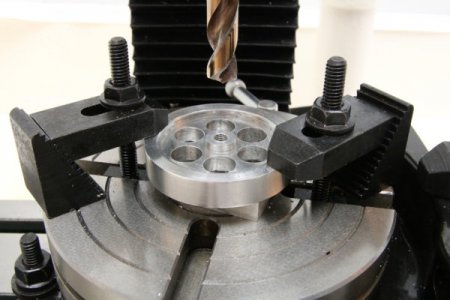
FlyWheelDrilled.JPG

I drilled 3/8" holes in the flywheel for the little wobbler steam engine I built a few weeks ago. I had this in mind from the moment I got it, so it's nice to have it done. Needs a little finish work now to debur the holes and clean up the edges of the wheel, but I'll get that done as soon as I can.

So, for anyone who cares, or has the RDX Rotary Table (or one like it) this the answer to some of the things I left hanging. Now I want to measure the backlash and rotational accuracy of the table.
 
All you wanted, and more!

You're miles ahead of me, but I'll be saving those (only watched the first). The way I think of it, I can hold something horizontally with my dial indicator and tell it to move 0.1 degree. At 3 inches from the center (it's a 6" table), the end should move 3 sine(.1) or .0052". If backlash is more than 1/10 of that (5 tenths) I think I'll see it. I could always make the distance longer by bouncing a laser off a mirror several feet onto a wall.
 
You're miles ahead of me, but I'll be saving those (only watched the first). The way I think of it, I can hold something horizontally with my dial indicator and tell it to move 0.1 degree. At 3 inches from the center (it's a 6" table), the end should move 3 sine(.1) or .0052". If backlash is more than 1/10 of that (5 tenths) I think I'll see it. I could always make the distance longer by bouncing a laser off a mirror several feet onto a wall.

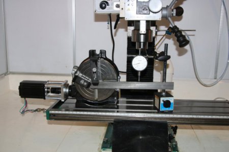
Backlash is easily measured with a 6" steel bar clamped to the table and a dial indicator. (The bar is longer than 6", but the indicator is set to measure movement there. 1 degree works out to .1047" and that was repeatable.)

MeasuringBacklash-4thAxis.JPG

I measured .038 degrees backlash. The table is 4 degrees per rotation of the shaft. I have the typical 200 step motors, so 4/200 is .02 degrees per step, indicating two steps of the motor taken up in backlash. I entered .038 in Mach3's backlash compensation and it seems to work repeatedly.

Onward...
 
Back
Top