Rhodes Shaper Rebuild

Re: Rhodes Shaper

Got to true the vice up.
The working face is close enough though I'll be rechecking everything later.
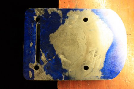
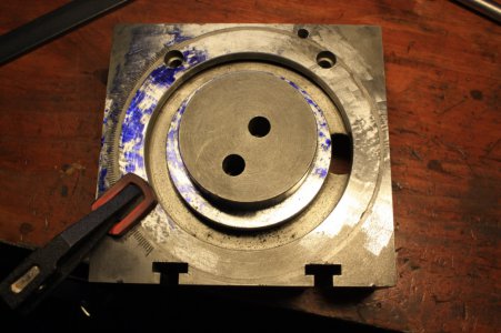
Started on the bottom of the vice. I already posted a pic showing it was high on one end.
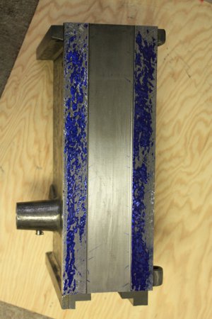
Here's how it blued.
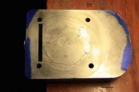
IMG_9501 - Copy.JPGThe high end is the slotted one.
To true it up, the high area needs to be reduced and the other end should roll in for a better blue. Plus, I'm checking it with the indicator to avoid rolling it side to side.
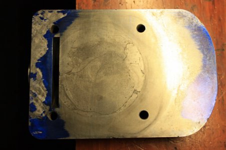
IMG_9503 - Copy.JPGA bit of improvement.
IMG_9507 - Copy.JPGA bit more.
You can see the mounting holes and lines where the base ring bolts up.
I got further along with this than the pics show.
Had to stop as I had some windows open and those high winds came back.
Found grit was landing on the plate and I couldn't keep it clean.

Checked out some of the bearing surface on top of the body casting.
Needed to know what I could use for a reference for the offside vertical face that the ram runs against.
Had to use a dry stone and lightly check for burrs.
IMG_9516 - Copy.JPG
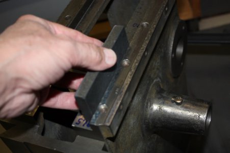
Here come those adjustable parallels again.
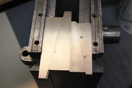
IMG_9510 - Copy.JPG
Unfortunately, I don't have a three to four inch mic. Have to make due with dial calipers.
I have seen inspectors check parts with calipers and repeatedly read them to the nearest tenth. That was in a controlled environment with all conditions being perfect and with parts that required close tolerance, they used a mic.
So check the calibration of those calipers before each use and once you get a feel for them you should be able to read between the lines for readings within a couple of tents.
Of course a mic would be much better.
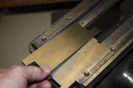
IMG_9522 - Copy.JPGHere, the outside end of the parallels will easly pick up while the inside stays lightly snug. Shows these ways are belled to the outside.

Here's how I stood the parallels to take readings. If they are properly set and the surfaces are true, you'll get them squarely set but I also checked with a square.
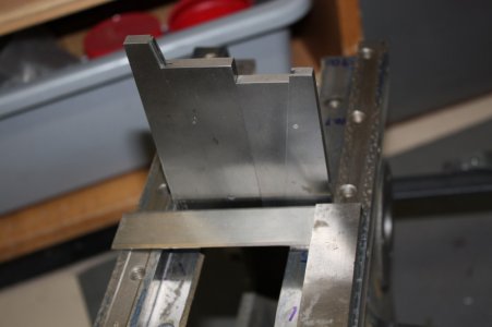
IMG_9515 - Copy.JPG
After checking both ends and the middle area, I decided the side opposite or, where the gib rests, could be used as a standard to keep the working side parallel.

Measuring down to the horizontal ways can be done this way while roughing in.
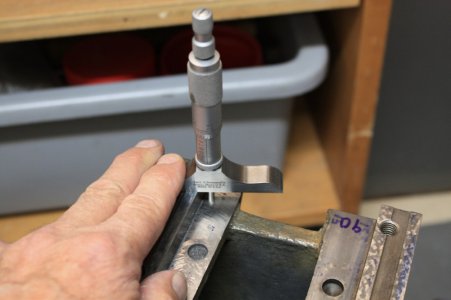
IMG_9509 - Copy.JPG

As it gets close, this is a better way to measure.
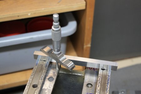
IMG_9508 - Copy.JPGA parallel spanning both sides to measure from.
Edit: Thought I ought to add that the final surface has to be completed using a master. In this case, that will be the ram after it's scraped in.
All this measuring just gets me two bearing areas that are fairly true to each other and flat so the blue will go faster.

IMG_9501 - Copy.JPG IMG_9503 - Copy.JPG IMG_9507 - Copy.JPG IMG_9510 - Copy.JPG IMG_9522 - Copy.JPG IMG_9516 - Copy.JPG IMG_9515 - Copy.JPG IMG_9508 - Copy.JPG IMG_9509 - Copy.JPG
 
Last edited:
Re: Rhodes Shaper

Truck lines require more information than I have to get a good estimate.
I've noted that companies that ship often could get it done for around $120 but that probably won't apply to the individual.
UPS could do it but that would cost more like 180 to 220 bucks and it would be best to break it down into three packages for handling.

Cost of moving things across the country really increases the overall price but not the value.
If I'm looking to get something heavy I try to get it at a retail that has regular shipping or Enco's free shipping days.
Looks like shipping is just too expensive.
Thanks for the offer.
I have agree, maybe some people on this site could you in getting closer. I would think that is your hope. Chester.
 
Re: Rhodes Shaper

It would be great if some one was making such a trip anyway and could handle it. I would gladly pay $100 bucks and buy em a meal. There's usually a bed and clean bath here. Hunting season can be kinda full but not always.
I live on the edge of nowhere in SW Colorado. Gotta drive 90 miles to see a stop lite.
Can't see it as likely that anyone is going to be crossing the country and pass very close to me.
I've been watching the local sales stuff just hoping some gems will turn up at a reasonable price.

Have passed up a few lathes because they were asking too much but there's not a lot of choices out this way and you have to drive at least 100 miles one way to see those.
One just has to learn to watch and wait.
 
Re: Rhodes Shaper

Looking for opinions and information on bearing surfaces.

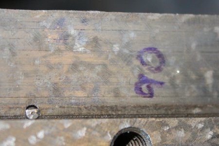
This is a closeup of the bearing surface for the ram.
IMG_9512-flake.jpgIt looks like a form of flaking to me but it has depth and can be felt running my fingers over it even though it's worn.

A bigger surprise to me is that the rams surface that slides over it also had the same flaked pattern.
I thought two sliding surfaces only needed one scraped for oil distribution.

Perhaps the pattern used provided a large bearing surface with reduced oil area so both surfaces so treated gave the largest acting bearing surface and good oiling.
Just wanted to know if someone could tell me how this pattern was produced and what you think about scaping both surfaces.

IMG_9512-flake.jpg
 
Re: Rhodes Shaper

Been awhile since I updated the post so felt I should show a bit of progress.
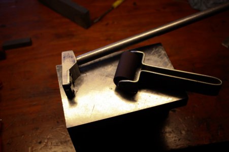
Have yet to purchase a good roller for spreading blue but used a salvaged roller from a bad printer to make one.
The rubber roller sections were only 1.4 inches wide so I just cut one off and drilled n bent a quick handle.
IMG_9551 - P.jpgThis shows the roller and my first gen pull scraper.
The roller works great and allows me to evenly spread a very thin layer of blue for finish scraping.
I have to be very careful with this scraper as the attach point for the handle is too high and when trying to pull too much material or when I'm tired I can cause it to roll and gouge.
Will have to make a better one soon.

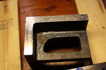
The tools are sitting on a 4" x 6" angle block which I'm scraping in.
The large surfaces are fairly well done.
When scraping the 4" x 6" flat I had some trouble as it has so much surface area that it wanted to float on the plate long before it was done.
As the surfaces get close to flat, the blue must be spread extra thin to get a good reading. So thin that it's hard to see on the part and the part has to sit long enough to settle onto the surface plate.
When I then moved the angle block to blue the high points, it would float again.
IMG_9561 - P.jpgTwo of the sides are getting close. I can still see some light in small gaps when placing them against the straight edge.
If the large flat areas are truly flat and at 90deg to each other and the sides are truly 90deg to both of the flats, then they will measure the same, side to side, at all points.
I took a few minutes to measure the sides and found that they are within a half thousanths.
That error will get better before I'm done.

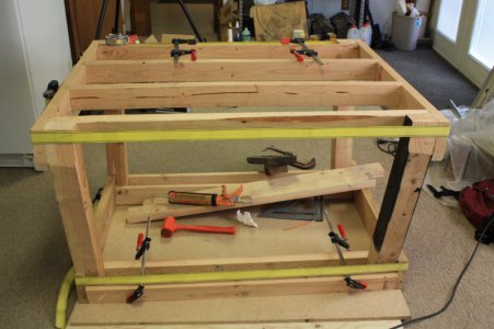
Am building a table to hold the surface plate, provide a solid area to hold parts being scraped, and store materials.
IMG_9533 - P.jpgMust admit that I'm one of those people who shouldn't be allowed around wood so please don't be too critical.
Will make drawers and use 100# slides. It will have an area to store material up to 3ft long as well.
The table top will overhang so it provides a good area to clamp parts and I can screw blocks n jigs to the table as needed.
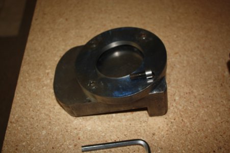
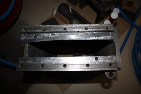
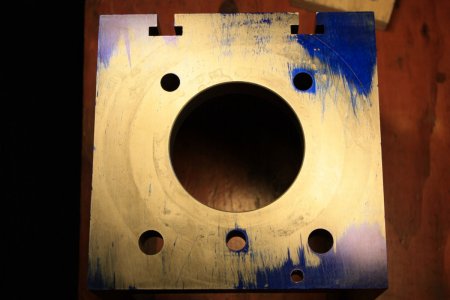
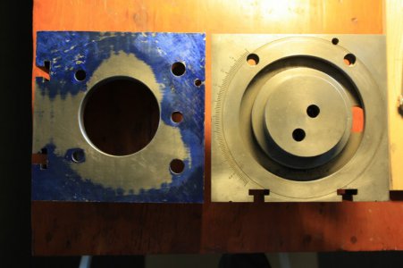
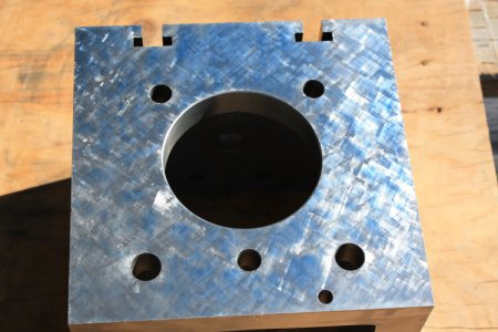
IMG_9565 - P.jpgI scraped the vice in and improved my scraping on the graduated ring that mounts to the bottom of the vise.
The bolt heads bound in the plate so I turned them down just a bit .
When bolted together, the error is about 0.0001" .
Recon that will do.
IMG_9279 - P.jpgAfter machining the flats and 60deg angle on my 26" long straight edge, I found it to be too heavy to comfortably handle.
The flats were machined close enough that a 1.5 mill feeler gauge wouldn't fit under them when I laid it on the surface plate.
After removing material to lighten it, it warped a bit but with my cheapo equipment I am just scraping rather than trying to machine it again.
IMG_9562 - P.jpgGot a ways to go on the 60deg face and am still roughing the flats.
Have put some scratches on the flats trying to scape too deep and found my scraper is slightly magnetic so I will have to get a de-magnatizer.
All part of the learning experience.
IMG_9571 - P.jpgThe horizontal ways have been rough scraped within a half thousant's.
The side gib will need to be replaced and it shows that the contact area is rather low.
Am considering adding more adjusting screws to keep a nice even pressure on the full length of the gib.
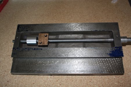
IMG_9569 - P.jpgAs the cross slide nut is worn I made a tight aluminum nut to check the cross slide screw.
The screw is 9/16"- 10tpi acme. Who would make such a small dia. acme thread?
Had to turn down a boring bar and make a really short threading tool to git er done.
The screw is worn and will have to be replaced but to thread a new one I'll have to have a follow rest, which I don't.

Looks as though I gotta build a follow rest but other projects must be completed first so for now I'll just machine a new nut thats as tight as possible and use the screw as is.
When I do make a new screw I'll try pre-hard 4140 and will alter the cross slide for a 5/8" diameter screw.
Seems to be just enough clearance to get away with it except the mount hole on the right will have to be opened up to accept the 5/8" bolt.
That hole is just a bit loose now so a larger dia. bolt would let me correct that as well.

The blue on the ways is the contact area so will have to scrape them in. I used a nice thick layer of blue too.
Seems almost every surface on this machine must be scraped.
Recon thats good practice.
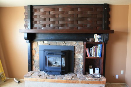
IMG_9573 - P.jpgNothing to do with metalwork but another project has been installing a pellet stove and re-building the fireplace.
The original fireplace was really plain and crappy looking and the mantle was so low that I couldn't open the hopper all the way to fill the stove with pellets.
I had some guests during elk hunting season last year and got them to carry in the stove. Let the healthy young guys do the heavy work.
The basket weave pattern isn't hard to make and hides a lot of my crappy wood working.
I raised the mantle a foot for clearance.
Still a lot of work to do on it.

IMG_9571 - P.jpg IMG_9569 - P.jpg IMG_9573 - P.jpg IMG_9551 - P.jpg IMG_9533 - P.jpg IMG_9562 - P.jpg IMG_9565 - P.jpg IMG_9279 - P.jpg IMG_9561 - P.jpg
 
Last edited:
Re: Rhodes Shaper

Was continuing to scrape in parts and when I had to add more blue to the plate I got it a bit thicker than wanted.
Rather than wiping the extra off I decided to blue the table.
IMG_9577 - P-01.jpgThis is what I found.
This surface mounts to the cross-slide and must be flat to use as a master to blue in the mating part.
IMG_9582 - P.jpgThis shows the table mounting surface, after a number of rounds of scraping, and it's mating part.
I started out scraping lightly but soon realized how far this has yet to go.
The other three table surfaces blued even worse and are so far out of square that they will have to be planed after the machine has been run in.
Judging from the surface quality and by how far out of square the table faces are, I think they were planed on the machine when it was worn and badly adjusted.

Still have a long way to go to complete my 60deg dovetail straightedge.
Started making it so I can scrape in my mill/drill ways and had planned to use it on the shaper.
After looking at the dovetail of the shaper, I thought to check that the straightedge would fit it.
Found that the shaper has a different angle and there's not enough clearance to cock the straightedge in for a blue check.
Seems scraping another straightedge is in my future.

IMG_9577 - P-01.jpg IMG_9582 - P.jpg
 
Re: Rhodes Shaper

IMG_9248 - P.jpgIMG_9247 - P.jpg
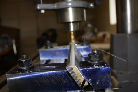
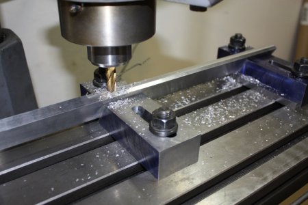
Here's the clamps I made to machine the 60deg angle for my straightedge.
One of those things I saw a picture of many years ago and said " That's neat! I gotta remember that."
Strange thing is, I did remember!

The shaper dovetail is 50deg and the straightedge will have to be 16" long.
May have to make it 3/4" thick which, if I squared and scraped the back edge, would make it useful for bluing in another cross-slide surface.
Not certain how to keep it stable if that thin.
Will take a closer look at it's design in the future.
Got plenty to keep busy with for some time.

IMG_9247 - P.jpg IMG_9248 - P.jpg
 
Jim, hope ya don't mind me adding "Rebuild" to your title? I just think more people will tune in. I had been just passing this thread by and popped in to see what is all about. Great stuff, keep it coming.
 
Oh! Thats where that came from.
The title is better now.
Thanks Randy.
 
IMG_9584 - P.jpgGot the blue so thin on the surface plate I can get very little on my finger when rubbing it across the plate.
Am surprised that the blue shows so well in the picture.
It was more clear when carried into direct sunlight but the camera sees it much better than my eyes.
Will go a few more rounds lightly scraping some high spots and then start the mating part.
Perhaps the table is picking up the blue so well because it wants to wring to the surface plate after it settles.

IMG_9586 - P.jpgFound heavy contact on the left and right sides.
The compass is pictured on the left.
Not wanting to scrape into the compass so I tried to tilt the part a bit by scraping deeper on the right side but the boss is holding it.
Cant have pressure on the boss and rabbit fit.
Checked again that the table mounting surface was square to the T-Slots. That looked good but I'm trying to think how I can better check it.
Will also need to measure how thick the casting is from this face to the back face. Well, I spose I shoulda done that before starting to scrape.

IMG_9574 - P.jpgGot a good start scraping the flat ways.
I first set it up on the surface plate and made checks for square to these faces.
They were setup to hold the outside end of the table up just a bit. Much as the mill knees are.
In this case, I think the ram will have just a little climb as it reaches out so the table is lifted on the outside to compensate.
The checks were done in 6 areas and I got 6 readings.
When sliding the straight edge against the face the gap was too small to get a feeler gauge in.
So, I trapped a 1 mill thick piece of shim stock between the straight edge and the face which let me use feeler gauges to check the gap at the top.
I could get a 1.5 mill gauge in at three points and a 2 mill gauge in at one point.
Two points wouldent allow the 1.5 mill gauge but a gap could be seen.

The clearance for the ram is set using shim stock which means it probably can set it to 1/2 mill or closer.
It has to have some room to move and for lubrication to travel but I'm not certain what it should be.
Even at 1/2 mill, I think the ram would lift less than that as it's trapped in such a long guide so I plan to go with 1/2 mill per ft on the ways.

After getting the face of the ways scraped close I found they bowed out and had to correct.
Then checked for the taper and found it was 1.5 mill per ft.
Am trying it again as I really want that 1/2 mill per ft.

At this point I've got many hours of scraping to do as well as build a 50 deg straight edge.
Will have to build 50 deg clamps to machine the angle.
Also have other projects going.
Better get back to it.

IMG_9584 - P.jpg IMG_9586 - P.jpg IMG_9574 - P.jpg
 
Back
Top