Well the rotary phase converter is running. This turned into quite a project in itself.
This was originally a
WNY panel, with the 20HP 3 phase motor from my Monarch 612 lathe set up as the idler motor. I set it up originally as a combined unit, with the idler and panel on a small frame I welded together, and a 3phase breaker panel. Here is that setup in the old building:
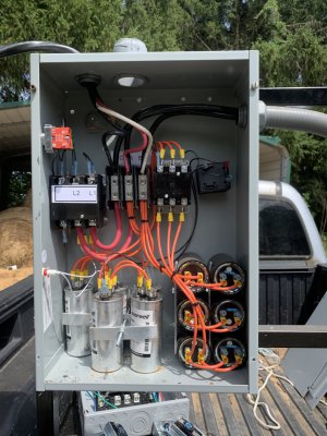
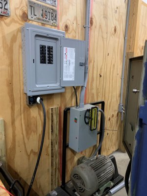
The contactor on the top left is the main on/off contactor. Contactor on the top, second from the right is the start capacitor contactor. The top rightmost thing is a voltage sensitive relay for detecting how long to leave the start capacitors engaged. The bottom left is the run capacitors (five silver cans standing upright). The six cans stacked on the bottom right are the start capacitors.
That original setup draws 209 amps (very briefly) at startup, which is not unrealistic for a 20HP idler but is a little higher than I'd like to see.
For the new shop, I wanted to
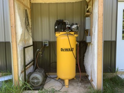
1) Use the existing RPC but put the idler in the external build-out shed that also houses the air compressor
2) Have the option to upgrade the RPC to include:
A second idler for increased capacity
A digital controlled option for balance capacitors,
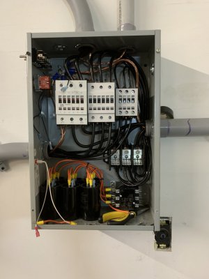
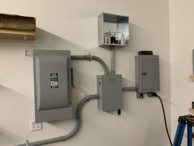
I started by getting a real cut-off switch to put in front of the RPC. I like being able to see the big red handle in the cut-off position when I'm working on it. That cutoff is wired to the main behind the drywall to a 100amp breaker in the main panel using 4/0 aluminum SEU. The original RPC panel is in the lower center. The far right is a small 3 phase breaker panel. The top center is an "expansion" panel for future digital controls. The conduit going off picture on the bottom left is to the idler, going through the wall a little off picture.
Figuring I'd need more space, I gutted the original panel and rebuilt it with the three WEG contactors plus the old start contactor. I upgraded the wiring from 6 ga copper to 2 ga copper into and out of the RPC. That will safely carry the 100 amps max from the main breaker on any leg through to the 3 phase breaker box. Here's the main RPC box rebuilt with the WEG contactors. The leftmost, 95 amp contactor is the main input on/off breaker. It switches the single phase input lines on/off. The third pole is used in a standard safety on/off latching in conjunction with momentary contact on/off switches. The middle contactor is a 60amp breaker to the 20HP idler. The rightmost contactor is currently unused but is there to support adding an additional 10HP idler. The start capacitors and associated contactor and voltage control relay are at the bottom. The run capacitors got moved to the expansion panel.
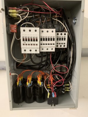
I added these three DPDT on/off/on switches. One for each new contactor. In the up position the contactors are controlled manually by red/greed on/off buttons. In the middle position they are off (the contactor can't be activated without changing the switch position). In the down position, the contactors are controlled by terminals in the expansion panel, which are currently not connected but allow for a future microcontroller to control the contactors.
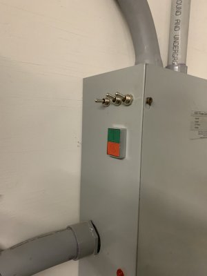
I also decided to add some
cheap volt/amp meters to the front panel so I could see the voltage and current on each of the three phase legs.
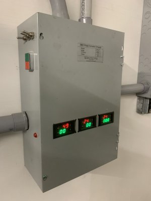
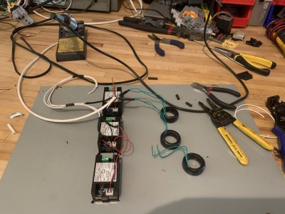
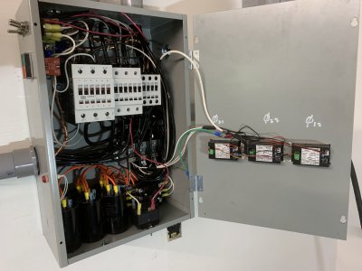
The numbers look strange, apparently the update strobing is slower than the smartphones camera shutter, but the numbers looked more reasonable in person. Red is voltage, with the leftmost being the line voltage and the other two being each line to generated leg. Green is the amperage. Nothing is running off the RPC so the output current is zero. Idling my K&T 3K's 10HP motor takes about 10 amps. These meters don't show power factor, which is a pretty complex issue for 3phase. I did convert the front of the panel from a screw on panel to a hinged panel as I otherwise worried the wires to the meters would get damaged if the panel were to hang off the wires when removed.
If I were to do this again I'd just have gone to a 24" x 24" main panel (the original panel is 12" x 18" IIRC). I would also add a small UL1077 2 pole breaker for the control circuits. If one of the small wires breaks loose and touches the frame, the only current limiter is the 100amp main breaker. I might also consider an output contactor. The idler should be spun up with no 3 phase load, which for now is up to the operator (error prone me) to assure that all 3 phase machines are off before starting the RPC. An output contactor would assure that is left open until the idler stabilizes. And it really wouldn't be a bad idea to have heaters (overloads) for each of the idler. I might also add an e-stop to the main contactor control if/when I start messing with digital controls, although that big red on/off handle is really the best e-stop.
As a side note, for those that made it this far, I've come into the shop on a couple mornings to find the vacuum cleaner running. I wonder how that happens? (Note the large on/off switch for the vacuum is right above the craftsman label, covered by some paws).
