My First Lathe - HF 9" x 20"

Well... I could not leave things alone... Saw a few folks installing RPM displays on these lathes... so I had to do the same.

Made a cutout on the side cover. Inserted the display there.
Made a small bracket out of aluminum for the hall sensor. Secured it with a longer bolt on the factory location for one of the bolts that holds the cover. Blue Loctite on everything...
JB weld for the magnet on the spindle...
Had an old 12 volt power supply from an ethernet switch that I had thrown away. Perfect!

I still need to install some wire clamps to permanently secure the wiring. Right now I just used some small binder clips (and removed the handles)... I also need to make a cover for the exposed electronics...

IMG_2351.jpeg


IMG_2352.jpeg


IMG_2358.jpeg


Last edited:
Please elaborate. That looks like a great idea!
Those are Harbor Freight 1" travel indicators ($17.00) held by slotted alum brackets to move to where ever you need them and I also have 2" and 4" indicators for the longer stuff, the brackets I just attached to existing holes and you can also use a mag base as each machine has it's own situation.
 
Also received a few things from Little Machine Shop... Handle for the knob I am making... Tool post (because it was faster than me modifying a bolt), and a carriage stop...

IMG_2366.jpeg


Also the lamp came in... Here you go, lamp in place, QCTP installed...

IMG_2369.jpeg


IMG_2372.jpeg


IMG_2370.jpeg
 
Let's get working on the knob replacement... my second project with the lathe... Mill machine was needed as well...

12 mm drill bit arrived... still needed to bring hole to spec by using some emery cloth with a rod... but got it to fit perfectly...

IMG_2373.jpeg


There are two positions on this knob, and a bearing ball with a spring and set screw... so needed to recreate that... I managed to set the bearing ball in place while sliding the knob... then tapped the knob and the ball left an indented mark on the knob.

IMG_2374.jpeg


IMG_2375.jpeg


Off to the milling machine to drill the hole... then M6 tap for the set screw that holds the spring and bearing ball in place...

IMG_2376.jpeg


In this photo you can see that the side of the stock has some nicks... I later ran it on the lathe and got rid of those...

IMG_2377.jpeg


IMG_2378.jpeg

IMG_2379.jpeg


Left to do is the side hole and tap for a set screw that will hold it against the shaft... And to figure out where and how to place the handle. I am thinking here at an angle facing forward... What do you guys think??

IMG_2383.jpeg
 
Those are Harbor Freight 1" travel indicators ($17.00) held by slotted alum brackets to move to where ever you need them and I also have 2" and 4" indicators for the longer stuff, the brackets I just attached to existing holes and you can also use a mag base as each machine has it's own situation.

I have the same bolt mounts... I will see if I have stock to make those. Can you give me the measurements of the material you use? Rough dimensions are fine. I just want to see what I need to start with and what dimensions I should be hitting...

I see several projects in that photo:

1. Dial indicator holder (mechanical DRO)
2. What is the reason I see folks installing bearings on here?? I will still need to replace the bolt that I got from Little Machine Shop. It does not comes out enough. And if installing bearings is a good modification to make, I will need that bolt to be longer to accommodate for those.
3. I like that!! Locking knob... and I will finally get to make a knurl!!! More details on this one please. Is there a hex bit in there? secured with a set screw?
4. Looks like another mount... a photo of this please?
5. Wait a minute!!! What!!!??? :D :grin big:

Dial Indicator Mount.jpeg
 
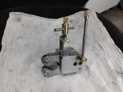
OK, dimensions for #1 and it's little brother #4 on the Z axis I will have to get when I'm at home. #2 is a 3/8 -16 stud threaded into the compound from a mill hold down dog set and the nut to fit it. #3 is a carriage lock knob for the Z axis which is just a knob I made pressed on over the allen head screw that was there. I see you noticed my broken lead screw handle, that's on my list:<) Yes, the QDTP is one I made from some ideas on the web I saw, I will search for the one that inspired me, I might still have the model too, will have to look. Yes to knurling:<) Here is a pick of that tool as you will need a scissor type vs a X axis pressure type, to rough on the lead screw. Also links to the making of most of this...


Edit, found the link....http://www.stubmandrel.co.uk/workshop/88-make-a-quick-change-toolpost
 

Attachments

  • Knurl-2.jpeg
    Knurl-2.jpeg
    484.2 KB · Views: 145
OK, dimensions for #1 and it's little brother #4 on the Z axis I will have to get when I'm at home. #2 is a 3/8 -16 stud threaded into the compound from a mill hold down dog set and the nut to fit it. #3 is a carriage lock knob for the Z axis which is just a knob I made pressed on over the allen head screw that was there. I see you noticed my broken lead screw handle, that's on my list:<) Yes, the QDTP is one I made from some ideas on the web I saw, I will search for the one that inspired me, I might still have the model too, will have to look. Yes to knurling:<) Here is a pick of that tool as you will need a scissor type vs a X axis pressure type, to rough on the lead screw. Also links to the making of most of this...


Edit, found the link....http://www.stubmandrel.co.uk/workshop/88-make-a-quick-change-toolpost

That is a beautiful work of mechanical art!!!

Knurl-Art.jpeg
 
Back
Top