G0704 CNC AC Servo Rebuild (Picture Heavy)

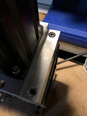
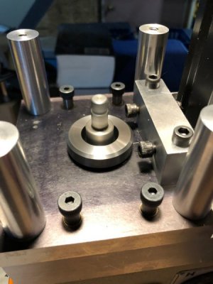
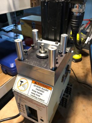
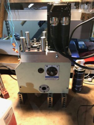
Got some new bolts in the mail and got the spindle assembled. Unfortunately, working just from a CAD model bit me again and not all of the mounting holes on the top of the spindle line up (guess the Chinese factories put holes wherever they please). I'm hoping I can open up the counterbored holes on my aluminum mount to get things positioned better. Of course now I don't have a mill to use so I'll have to butcher it on the drill press...

I was able to get the motor and belt mounted on 3 out of the 4 screws and got it up and running. I am slowly breaking in the bearings/belt and taking detailed measurements of torque consumption, temperature, and noise as I work up in speed. I'll post those results when I'm done testing, but I can say right now that it is a LOT quieter. At 1500rpm it measures about 10dBA less that my lathe running at 550rpm with no gears engaged. The lathe is quite comfortable to run without earplugs.

I have only run it up to 1500rpm so far, but the highest bearing temp was 89 degrees in a 72 degree ambient temp (I'm right next to the furnace).

All in all it seems to be going well, stay tuned for test results.
 
So I haven't had so much time to work on this at night but here are some basic tests up to 1750 RPM.

Original Velocity Tuning Gains:
P: 200
I: 20
D: 0
zero speed response kind of spongy, small surging sounds at speed, velocity drops under simulated load.

Ambient Temp: 72 deg - Fluke IR Temp gun

Ambient Noise: 34 dBA (Furnace Off) "Wisper"
Ambient Noise: 67 dBA (Furnace On) "Traffic"
Ambient Noise: 79 dBA (Lathe on) "Alarm Clocks"
Noise readings taken at 1', microphone pointed away from source

All tests run for 20 minutes or longer for reading to reach steady state.

Test 1: 100rpm
Starting Current 0.98A
Lower Bearing Temp: 74.0 deg
Upper Bearing Temp: 72.0 deg
Case Temp: 72.0 deg
Noise: 39 dBA "Quiet Library"

Test 2: 200rpm
Starting Current 1.19A dropped to 1.16A
Lower Bearing Temp: 74.0 deg
Upper Bearing Temp: 73.0 deg
Case Temp: 73.4 deg
Noise: 45 dBA "Quiet Street"

Test 3: 300rpm
Starting Current 1.286A dropped to 1.168A
Lower Bearing Temp: 74 deg
Upper Bearing Temp: 75.8 deg
Case Temp: 75.2 deg
Sound Level: 50 dBA "Quiet Street"

Test 4: 400rpm
Starting Current 1.254A dropped to 1.170A
Lower Bearing Temp: 76 deg
Upper Bearing Temp: 77.4 deg
Case Temp: 77.4 deg
Sound Level: 55 dBA "Normal Conversation"

Test 5: 500rpm
Starting Current 1.274A dropped to 1.218A
Lower Bearing Temp: 77 deg
Upper Bearing Temp: 79.2 deg
Case Temp: 77 deg
Sound Level: 56 dBA "Normal Conversation"

Test 5: 750rpm
Starting Current 1.349A dropped to 1.274A
Lower Bearing Temp: 81.2 deg
Upper Bearing Temp: 82.6 deg
Case Temp: 79.2 deg
Motor Temp: 84.2 deg
Sound Level: 68 dBA "Traffic"
Noticable 3-5Hz surging with higher frequencies. Kinda annoying

Test 6: 1000rpm
Starting Current 1.360A dropped to 1.299A
Lower Bearing Temp: 85 deg
Upper Bearing Temp: 86.4 deg
Case Temp: 82.4 deg
Motor Temp: 88 deg
Sound Level: 68 dBA "Traffic"
Much smoother sounding than 750rpm
Quieter than my lathe at 550rpm and no gears engaged

Test 6: 1250rpm
Starting Current 1.480A dropped to 1.375 A
Lower Bearing Temp: 87.2 deg
Upper Bearing Temp: 89 deg
Case Temp: 84.6 deg
Motor Temp: 90.6 deg
Sound Level: 72 dBA
Higher pitched than 1000rpm, slight high pitched squeaking can be heard
Quieter than my lathe at 550rpm and no gears engaged

Test 7: 1500rpm
Starting Current 1.55A dropped to 1.464A Cold Start after sitting all day
Lower Bearing Temp: 89 deg
Upper Bearing Temp: 90.6 deg
Case Temp: 84.0 deg
Motor Temp: 92.8 deg
Sound Level: 72 dBA
Occassional Fluttering sound?

Shortly after starting the 1750 rpm test, I head a somewhat loud clicking sound. Due to the hole misalignment to the casting, I did not have the top hat installed above the spindle pulley which allowed the pulley to slightly work itself up the spindle shaft until the key was just kissing the housing. I stopped the spindle and installed the top hat. At the same time I also released belt tension so the numbers following this point will no longer be correlated to the above testing. That being said, the lower belt tension gives a much smoother and quieter running noise. I can pretty much only hear the motor noises instead of the belt noises! I made sure everything was set up correctly and ran at a full range of speeds up to 3000rpm. It all sounds amazing. I also retuned after turning on the low pass filter. Here are the new gains:
P: 1000
I: 280
D: 25
LPF Bandwidth: 350Hz

Now the spindle is incredibly stiff and the only compliance is the slightly looser belt. There are no unwanted resonances or oscillations. All of the velocity surging is gone and it maintains speed within +/- 1 rpm even when simulated loads are applied (I grab the spindle nose by hand).

As a benefit, the lower belt tension reduced the running current draw down to about 0.9A after taking off motor bearing losses. This equates to a belt drive (and spindle bearing) efficiency of around 90-92%. I'm pretty pleased with that.

I also got my hands on a calibrated Fluke temp gun, so the numbers are reporting a touch higher but I trust them.

Test 7: 1750rpm
Starting Current 1.15A Significantly loosened belt
Lower Bearing Temp: 96 deg
Upper Bearing Temp: 98 deg
Case Temp: 89.8 deg
Motor Temp: 98 deg
Sound Level: 77 dBA
Adjusted belt and installed top hat. Sound is very very smooth. Total volume registers higher, but upper assembly is removed and everything sounds much better.

I intend to continue testing up to 3000 rpm this weekend as well as finish the electrical cabinet and get it installed.
 
Last edited:
As always, everything takes longer than I planned, however I did have a very productive weekend.

I started by moving the smoothstepper from my old enclosure to the new one (thereby committing to the new panel).

286916

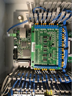
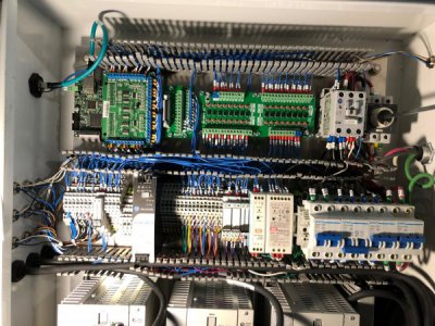
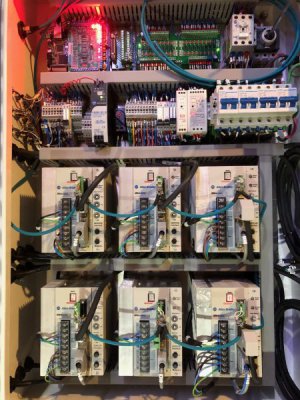
I completed wiring to the 3rd smoothstepper port, added all the relays, and finished the terminal wiring. I opted to add an additional 2 relays so that the power draw bar solenoids were not powered directly from the voltage converter boards.

286917

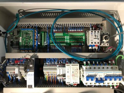
The extra blue cable is RS485 over Cat 5 cable for communications to the drives. I need to drill 2 new cable gland entries, and when those are done, I will pull this cable out to the computer. Hidden in shadow next to the 1606 AB power supply is a thermostat which will shutdown the drives should the temperature exceed 130*F (The limit for non-derated drive operation).

286921

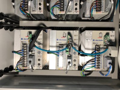
Here you can see the RS485 network between the drives. In the short term, this allows me to talk to all 6 drives through their configuration software Ultraware, but hopefully some scripting though mach will allow me to pull diagnostics and set parameters on the fly. I know the drives are capable, but just need to learn LUA. If anyone has experience with this, please message me!

286923

And to finish off, I wired up the 50A power connector and ran hooked up 240V power. After a careful startup, the panel was live with no blown components or tripped breakers. The power supplies were adjusted to get the correct voltage under load. It is pretty!

286924

EDIT: I also added two new wires to the spindle drive I/O connector (bottom right, thin grey cable, blue wires zip-tied to it). These are the spindle motor encoder output which connects to the larger 2 relays and allows electronic gearing between the spindle and the Z or A axes (rigid tapping or hobbing).

EDIT: The curly Q red wire coming off of the power supply is a temporary wire that will be replaced once the timing relay arrives. This will let me power the PC even without that component.

At this point, I am going to put the electrical panel on hold until the motors are completely mounted.

I still need to correct the poor mounting hole placement for the spindle housing, hopefully that will be done tonight.
 
Got the spindle mount fixed up last night.

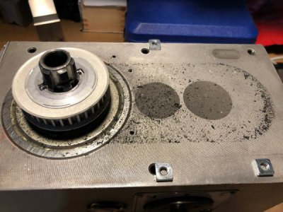
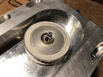
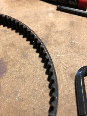
First thing I did was tear down the existing setup. When I did, I found a substantial amount of belt dust inside the housing. I'm hoping this was from when I forgot to install the top hat and the spindle pulley worked itself loose. I cleaned it all up and I will check on it in the future. Those pulleys should be axially aligned within a few thou and completely parallel.

286956

286957

286958

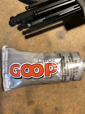
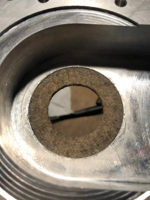
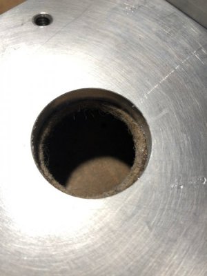
My design includes a felt washer that gently rubs against the top hat OD to help seal in noise. The original adhesive back didn't cut it, so I used some GOOP to glue it on.

286959
286960
286961

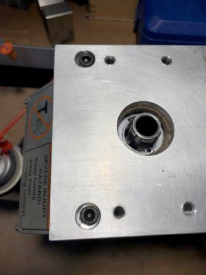
From there I used some reamers, and endmill, and a few drills in my cordless drill to open up the mounting holes and counterbores. It isn't very pretty this way, but it will all be covered by other components. I still can only get 3 screws to go in, but at least it lines up now. I could file the other hole down the road, but it isn't needed.

286962

286963

From there, the upper puller plate assembly is mounted. There is only a few thou clearance around the top hat, so alignment is critical. The pneumatic cylinder is mounted on these posts.

286964

286965

286966

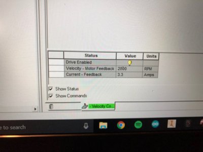
Finally I ran the spindle at 2800 rpm (max at 120VAC) for around an hour. The bearing temp rose to around 130F. This isn't crazy but a bit higher than I was hoping for. The Kluber IsoFlex NBU 15 grease has a service temperature up to 130C (266F) and the bearings have a service temperature of 250F which is the limit for the phenolic cage. I hope to not get anywhere near this, but it does give me a hard limit.

Since I have been adjusting so many things, I'm going to hold off on the running torque/temperature measurements until the assembly is complete.

As a note, I have found that the timing belt runs the smoothest with a very low tension. As I get it tighter, the taught belt acts like a guitar string and generates significantly more noise. Unless I have issues with compliance in the spindle when stationary or with teeth jumping under high load, I will leave the belt just hand tight. It also consumes far fewer amps when a touch looser.

286967
 
Quick question... does everyone like the pictures in the posts or would pure text be preferred?
 
does everyone like the pictures in the posts or would pure text be preferred

This is a trick question, right? :)

gotta have pictures! I think that your pictures are great. The quantity and quality. Very easy to see what you are doing and appreciate the quality of the rebuild.
 
So I switched gears last night and started work on the actual machine:)

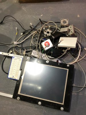
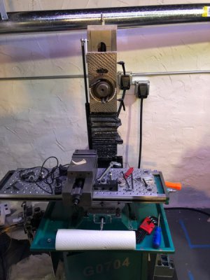
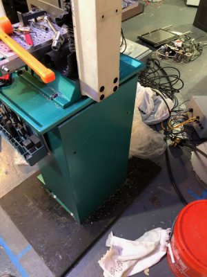
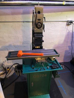
I started by removing the touchscreen, stepper motors, motor mounts, cables, and the old PC. It occurred to me that this might be the last time I ever see Windows XP. Kinda a sad thought.

287020

She looks a little naked.

287021

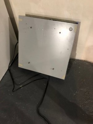
Next the old electrical panel was removed by loosening the 4 studs that were attached to the sheet metal base.

287022

287023

Mind you that I cleaned this machine spotless and there was still a million chips hiding everywhere. I removed the fixture base plate from my table and gave it another cleaning.

287024

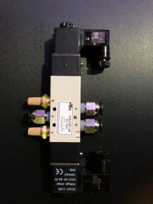
I got the solenoid valve for the power drawbar in the mail from AutomationDirect. It is a 5 port, 4 way, 3 position, center exhausting valve. It uses 2 24V outputs and fits 1/4" tubing.

287025

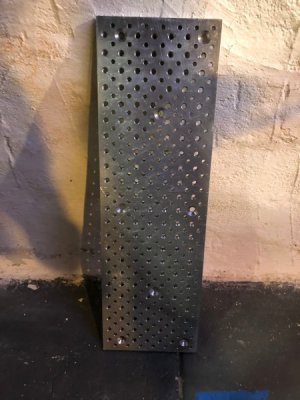
And here is a quick shot of the fixture base plate. It is 3/4" aluminum and has a 1" grid of 3/8-16 tapped holes and and offset 1" grid of reamed .251 dowel pin holes. I made this when I had access to a large kneemill at school and it has been one of the most useful things I've gotten for this machine. The cast iron table of the mill is getting a little stained from the coolant that pools in the holes. This used to bother me, but now that I keep this plate on the machine 100% of the time, it is no big deal. It mounts with 6-8 Tee nuts and flat head screws.

287026

Being unsure of the alignment of the panel, mill, and steel base plate, I maneuvered the control panel around to the back of the machine and roped it in place. Holes were laid out onto the steel baseplate.

Although I have no way to actually weigh this panel, based on my CAD model and how hard it is to move, I think it weighs between 150 and 200lbs. I certainly can't lift it , but if I go slow I can "walk" it on the bottom edge to wherever I need it to go. That being said, I was soaked in sweat by the end of the night. Didn't help I went rock climbing right after work.

287027

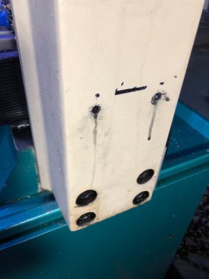
I reused the square aluminum tubing from the old monitor mount to hold the panel. One was screwed into the steel bottom plate (man that was hard to drill and tap), and the other screwed into the bottom of the machine column.

287028

Cast Iron taps like butter.

287029

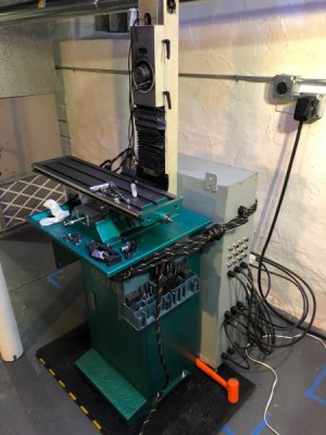
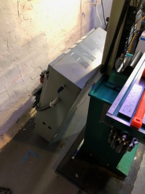
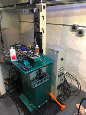
And here it is mounted. I wish I would have drilled the 2 new cable glands into the panel first, but it will be fine. I got excited:)

The panel door should just clear the wall.

287030

BTW, I'll be cleaning up the original CNC components and put them up for sale at a really good price. If anyone wants anything, just let me know.

Mike
 
Back
Top