G0704 CNC AC Servo Rebuild (Picture Heavy)

Well I have been doing a lot of redesign on my 4th axis since I am now getting serious about building it.

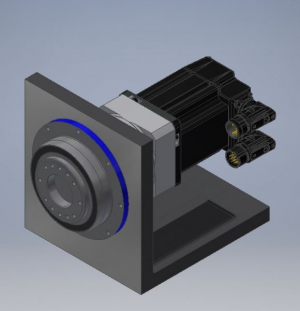
Here was the mock-up proof of concept design:
1564675123327.png

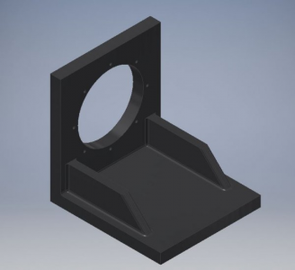
Notice almost everything is missing including mounting holes and the homing proximity sensor. Here is the cast iron angle plate as machined.
1564675187428.png

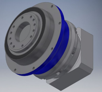
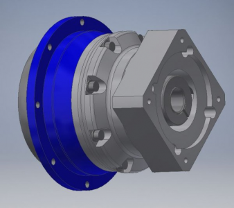
Here is the Alpha Wittenstein TP+ 1:31 gearbox I am using
1564676932391.png

1564676945494.png

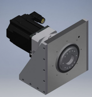
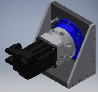
Here is a picture from partway through the design. Notably there have been side plates added, the gearbox is now mounted from the rear, and the Balluff inductive proximity sensor has been added.
1564677011269.png

1564677017572.png

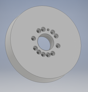
Next I designed a cast iron faceplate for this unit which will allow mounting of various fixtures including lathe chucks and tombstones.
1564675234361.png

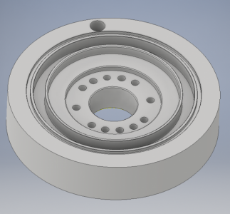
The rear of this faceplate is quite complicated due to grooves for sealing rings. As I have continued with the design, I am pretty sure I will remove the seals and rely on the seal integral to the gearbox.
1564677166139.png

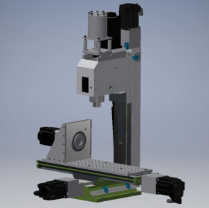
Here is a mock-up of the design on my G0704. Note that the model of the rest of the machine doesn't include the most up to date spindle design or limit switch mounting.
1564677121080.png

After this point I shortened the assembly by 1/2" and updated the mounting holes. I intend to further update it to include a carry handle on top and provisions for a sheet metal cover. I also need to model mounting features onto the faceplate.

I'm currently worried about weight. This unit as it is modeled comes in just shy of 60 pounds. This is a lot of weight to be hanging off of the end of such a small mill.

Open to design ideas!

Mike
 
It might be crazy and I have not seen anyone else do this, but could you rig a counterbalance weight to remove say, half of the weight of the 4th axis drive?
 
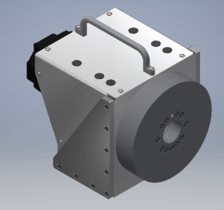
Getting close to the final design here.

Since the last version:
  • Simplified the faceplate by removing the V ring seal
  • Shortened the entire assembly to 7.5" plus the removable carry handle
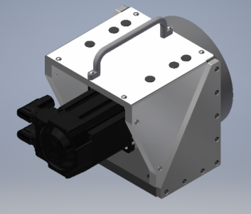
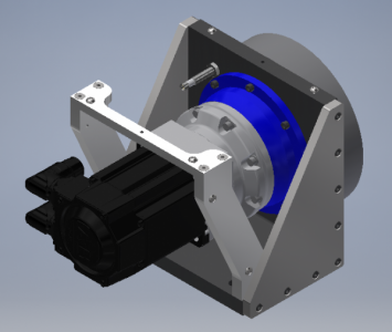
  • Added an aluminum truss structure to support the carry handle and sheet metal cover

The black dots are plastic caps to cover holes in the cover to allow access to the mounting screws in the angle plate

1564758890202.png

The back is left open for ease of manufacturing. Total weight is now 50lbs + whatever chuck or workholding gets attached.

1564758908991.png

Here is the truss structure. I could machine out a little material to save weight, but it isn't needed.

1564758923731.png

The only considerations I have left are wiring routing. I have a bulkhead connector for the servo cables if I want to make them externally dis-connectable. Same thing with the proximity sensor. Alternatively, I could always leave this connected and powered on, but set it behind the machine when not in use.
 
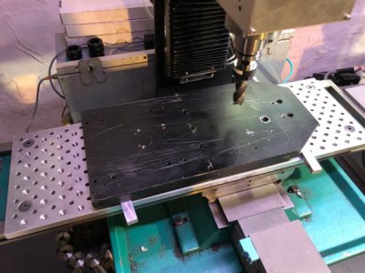
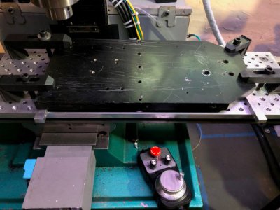
I started working on some of the parts for this 4th axis. The handle risers and side plates need to be machined from plate stock, but there is full machining of the perimeter so normal vise clamping wouldn't work. A while ago I had machined a tooling baseplate for my mill on a large knee mill with a tenths DRO and a tapping head (that was a long day...). My intention had always been that I could build fixtures onto the baseplate that could be accurately removed and remounted, but until yesterday, that had never happened.

I decided a large piece of sacrificial aluminum plate could be used to mount the stock for these components through their drilled features. I searched around a found a 7x16x0.75" plate of anodized aluminum (already full of holes making it useless for stock) that came from a professional CNC router I helped someone disassemble.

Plate 1.jpg

The plate was jacked up on aluminum spacing parallels, indicated parallel, and clamped to the tooling plate below.

Plate 2.jpg

I then wrote a 5 tool program to spot, drill and counterbore 6 mounting holes for 3/8-16 SCHS and cut two .2505" reamed dowel pin holes for alignment.

The program ran great and I programmed much more ... exciting ... feeds and speeds than I normally would have done. Everything ran great. I'm learning that I baby this machine far too much.

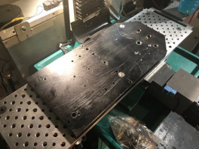
To my amazement, the plate slid perfectly onto the two dowel pins located 12 inches apart. I know the holes in the baseplate will drilled and reamed to .0001" positioning on the big knee mill (take that with a grain of salt) so this means that my CNC cut two features within .0005"/12" which was an order of magnitude more accurate than I expected. I don't believe the machine could cut any feature within this (in fact I know it can't), but I am just excited that this worked so well :D

Plate 3.jpg

Here it is all mounted (well missing 3 screws, but still). The next step will be to drill and tap the holes for the handle risers and get to work!
 
While you're at it drill some 1/8" holes with a good drill (or ream them) along the X and Y axis. Use brass pins (cut from stock) as locators so stock can be quickly aligned with the axis rather than bumping it in. And don't drill all the way through so the pins don't fall out.

Fly cut the surface, and you now have an excellent spoilboard for the 'tape and superglue' workholding trick.

Brass pins so if you forget to take them out before machining they just vaporize. Better than leaving a hardened dowel pin in there...
 
Hi All,

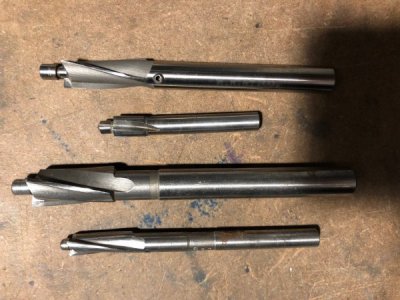
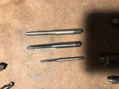
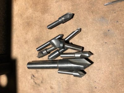
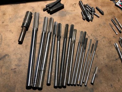
Have a month of weddings on the weekends and work travel in the week so forget having shop time (ugh). I got a small bit of tooling from a company which was going out of business after the owner passed away.

01.jpg

02.jpg

03.jpg

04.jpg

Nothing to write home about, but I didn't have any fractional reamers, so these are a very welcome set. There's a mismatched set from 1/4" to 7/8" and they're pretty sharp.

Still haven't run any of the parts for the 4th axis, but I have some of the code done in MasterCAM and the tooling plate all set up. I'm hoping to get this 4th axis going again soon.

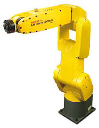
Totally off topic, but I never really jumped into math (for the sake of math) while I was studying Engineering in college. Since I graduated I have gotten very interested in industrial robotics and kinematics and have spent a LOT of time learning the math of robotics motion control and I LOVE IT. Seriously some of the hardest and most interesting stuff I've ever tried to learn. Anyways I've been looking for a used robot for years and just couldn't find anything that I could afford or reasonably play with at home. I did find a Fanuc robot not too far from where I live that I am going to try to pick up. Everyone cross their fingers for me.

1566218725477.png
 

I wish. They've only had some monster sized robots for the past year or so. That or they are kidding themselves on the price. This is from some random manufacturing company in western Ohio.
 
I'm probably going down to HGR soon to pick up some electrical stuff (enclosures, etc). I may check out the robot section because I suspect there are a few harmonic drives hiding inside some of the $69 'robot wrists' and similar.

That, and there's a giant planetary gear assembly for about $50 labeled as 'bearing assembly.'

I really need more time and space...sigh.
 
Back
Top