Fusion Browser Explanation for a beginner ???

File>New Design

Or Click the + tab to the right of the current drawing tab.
 
File>New Design, then it asks from design or animation?
 
Ok, not a bad start.

First off what you are calling "drawings" are actually designs. A design contains sketches, bodies and sub-components (and a lot more). So:

The data panel shows an open folder (the house / Bandsaw upper guide). Bandsaw upper guide s a folder (the house is "home" the top level of all your collection of designs - this is pretty much exactly like files on your computer).

In the bandsaw upper guide folder, you have a single design of a bearing that you got from McMaster.

That's the data panel.

You have opened up the ball bearing design and it is in a tab on the right side (you only have one design open, so only one tab. If you open more you will get a tab for each.

The bearing open design window has the "borwser" tree showing on the left side. This browser tree starts with the root of the ball bearing design.

The design contains exactly one component, the full ball bearing - it's the node labeled 661k8..... (part number). If you open that up you will find multiple bodies that make up the ball bearing component. Shell, race, balls, gasket etc. whatever. McMaster has provided the ball bearing model as a single component, contained in a design file. This makes it easy for you to use the ball bearing component in YOUR design. Leave ball bearing design alone - you don't want to change it as it represents a physical part you have no control over. You just want to use it.

Now -
Create a new design, Call it Upper Guide Assembly (or whatever) it's going to be the collection of stuff that you need to design to make the upper guide. Go ahead and save with the name (I think that might be required before you can insert any other components, maybe not).

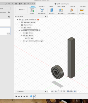
In this design, right click the root of the browser tree (top box with the design name) and select "create new component" Just fill in the name with something - I used "adjustable bar"

Add a rectangular body that you will eventually attach ball bearings to, don't worry about the size, details shape whatever, you can get that right later.

Notice that you have to have the component selected to add a body to it - the "adjustable bar" box is highlighted and there is a circle with a dot in it following it. This indicates that the component is "activated".

You can now right click the ball bearing DESIGN in the data panel and select "insert into current design"

You should end up with something like this:

add comp.png

I just used the "insert" pull down from the design tab bar and directly inserted the part from McMaster. Because I did it this way it just got directly inserted into my design without have to have an independent design file in the data browser / project folder.
 
What is the difference between the two? To me it seems the I want a new drawing, this is so confusing.
 
You work on Designs on your screen

This is a Drawing, derived from a Design
1674937712242.png
 
The primary function of fusion is to build cad MODLES - called designs. A drawing can then be produced from the model and printed for use as documentation or shop drawings. You start with a model and create drawings. The create drawing function is used to create proper drawings to industry standards FROM a design.

When creating a design, you can (do) create sketches that help you define the design. The sketches are part of the design and are often used derive features of the design from them (bodies, holes etc.). Because Fusion is parametric, you can go back and edit a sketch and your changes will propagate to features that have been derived from the sketch. It is extremely powerful once you get your head wrapped around it.

The language and teams are based on what is commonly used in industry CAD/CAM/Design etc. There is a lot there and a lot of basics to wrap your head around. Many of the terms have industry specific meaning. I had a hard time with that aspect of it when I started out also.

Additionally, each CAD vendor tends to develop and refine their own concepts based on what is common.
 
Ok, not a bad start.

First off what you are calling "drawings" are actually designs. A design contains sketches, bodies and sub-components (and a lot more). So:

The data panel shows an open folder (the house / Bandsaw upper guide). Bandsaw upper guide s a folder (the house is "home" the top level of all your collection of designs - this is pretty much exactly like files on your computer).

In the bandsaw upper guide folder, you have a single design of a bearing that you got from McMaster.

That's the data panel.

You have opened up the ball bearing design and it is in a tab on the right side (you only have one design open, so only one tab. If you open more you will get a tab for each.

The bearing open design window has the "borwser" tree showing on the left side. This browser tree starts with the root of the ball bearing design.

The design contains exactly one component, the full ball bearing - it's the node labeled 661k8..... (part number). If you open that up you will find multiple bodies that make up the ball bearing component. Shell, race, balls, gasket etc. whatever. McMaster has provided the ball bearing model as a single component, contained in a design file. This makes it easy for you to use the ball bearing component in YOUR design. Leave ball bearing design alone - you don't want to change it as it represents a physical part you have no control over. You just want to use it.

Now -
Create a new design, Call it Upper Guide Assembly (or whatever) it's going to be the collection of stuff that you need to design to make the upper guide. Go ahead and save with the name (I think that might be required before you can insert any other components, maybe not).

In this design, right click the root of the browser tree (top box with the design name) and select "create new component" Just fill in the name with something - I used "adjustable bar"

Add a rectangular body that you will eventually attach ball bearings to, don't worry about the size, details shape whatever, you can get that right later.

Notice that you have to have the component selected to add a body to it - the "adjustable bar" box is highlighted and there is a circle with a dot in it following it. This indicates that the component is "activated".

You can now right click the ball bearing DESIGN in the data panel and select "insert into current design"

You should end up with something like this:

View attachment 435303

I just used the "insert" pull down from the design tab bar and directly inserted the part from McMaster. Because I did it this way it just got directly inserted into my design without have to have an independent design file in the data browser / project folder.
Lots to take in! I don't get this statement "design tab bar" where is this?
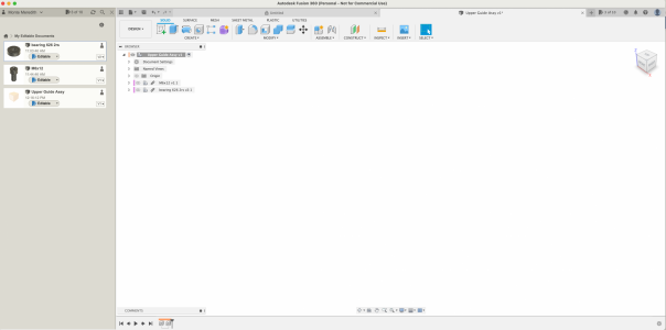
Here is what I have so far, I noticed that my browser doesn't look like yours as far as your ball bearing is under your adjustable bar.
Screen Shot 2023-01-28 at 12.49.04 PM.png
 
You are all set, you have a design that has two components added to it, the bearing and the bolt.

However - You have them all invisible!!!! you need to click the little eye ball icons in the browser tree in front of each component.

A couple of other things:
See how the components have little chain link icons? That indicates that they are not "in" your design but links to independent designs. You can't directly change the link components, you can only use them and copies of them in your design. This is what you want.

Do what I said before, Right click the root of the browser tree (top block) and create a new component. Call it slide arm or support or what ever. It will show up in the browser tree and the block icon after the eyeball will look like a box instead of a couple of boxes or L shape. There also won't be a link icon either.

I think the difference between the icons multiple boxes (L shape) vs single box just means that there are multiple subcomponents. Expand them and see what's in them.

The biggest thing right now is you have visibility turned off.
 
Back
Top