Five Cylinder Radial With Ohc

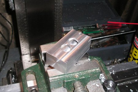
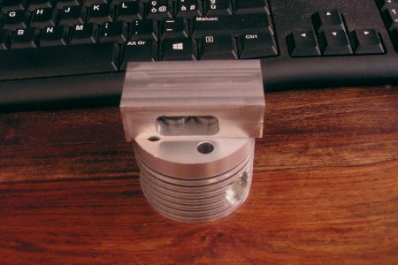
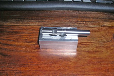
The next step was to cut the two holes for the cam followers.
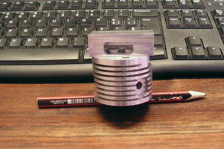
Then mill the access port in the side to allow the valve clearances to be set, the cover for this port will hold a felt pad to lubricate the cam and follower. Cylinders No 1 - 4 - 5 have the port on the right hand side No 2 - 3 have it on the left, Looking from the front of the engine.
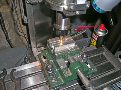
P1013274.JPG

p1013275.JPG

P1013278.JPG
 
Brian,

I have been following your progress from the beginning. I am very impressed by your work. Your progress has made me try harder to be a better amateur machinist. Thank you so much for continuing this build log.

Cheers,
Tom
 
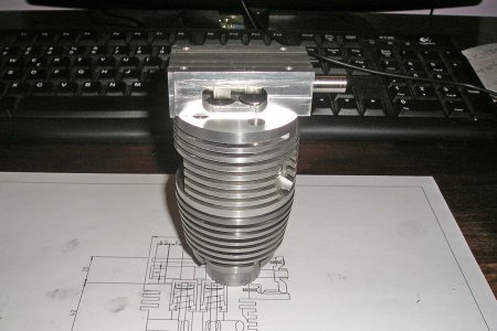
The next stage is to drill and tap the 3mm holes for the cambox mounting screws. but first I have to ensure that the two parts align properly.
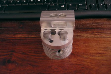
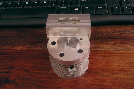
To achieve this a pair of stepped dowels where made that fit the bore of the cam follower and the clearance holes in the base of the cambox to provide a positive location, perfectly in alignment.
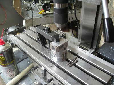
Now I can drill through both tapping size. then open out the holes in the cambox to just clear the screws and counter bore to recess the heads.

p1013279.JPG

p1013280.JPG

P1013281.JPG

Brian.
 
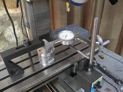
Following on from the last post ,The head and cam box was aligned very carefully on the mill
and the holes drilled relying on the edge finder and I Gaging for positioning.
On one side the holes are very close to the edge of the access port so a pilot drill was used first then the tapping size drill.
The clearance holes in the cam box where drilled slightly undersize without disturbing the settings, to the exact depth of the box then reamed after removal from the mill
P1013282.JPG

P1013283.JPG

Slowly Slowly Brian.
 
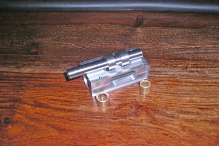
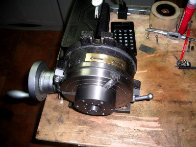
Todays contribution was to make the blank for the cam shaft. Prior to cutting the cams I have a small mod to do to the rotary table to make life easier. and repeatable.
The Oilite bearings have arrived , only awaiting the 2.5mm screws and taps.

Brian.

P1013291.JPG
 
Ok The first part of the job is done the R T now has a new adjustable mark . I have always wanted a mark to make life easier when the R T is vertical But to may well ask what the %^$# is Brian up to having a mark that is adjustable.
P1013292.JPG

When I cut the cams the angular relationship between the two is 107° so I will set the new mark 107° on from the normal zero mark.
Then cut the first cam From 0° using the normal zero mark. then move 0° to the new mark and use the same set of figures to make the second cam, No mental gymnastics necessary
Just so you know what I am up to.
.Brian.
 
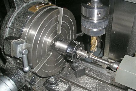
Cutting the cams, It took a while but now I have the settings for the other 4 when the time comes.
Tomorrow I will reduce the shaft to fit the bearings.
Brian.
P1013293.JPG

P1013295.JPG
 
And now it all starts to go together, but I am waiting for the screws and the taps, when I have it fastened
It will be possible to cut the valves to length and set the valve lash.
The top spring cups also have to be made.
P1013296.JPG


A little progress every day. Brian.
 
Looking good Brian! I have a local acquaintance who is one of those 'if it ain't made in the USA..." types who is a nice guy, but he's always giving me lip about my 'little' import machines and keeps asking when I'm going to buy 'real machines' to make stuff with.

So I sent him a link to your build thread here (as well as one of Bill G's and Mark's build threads) and started ribbing him about 'real' machinists can make good stuff on pretty much anything. I also said something like "put up or shut up" (good naturedly of course), so now he's looking at trying his hand at one of those radial engine kits from Ageless Engines.

This could get interesting... ;)
 
Hi Bill
There is none so blind as those that will not see
Waiting and a watching Bill
Brian.
 
Back
Top