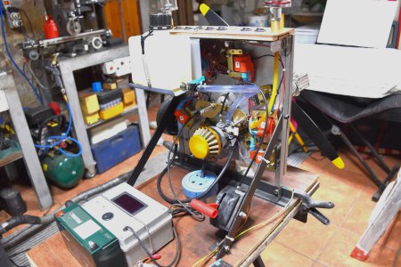
Five Cylinder Radial With Ohc

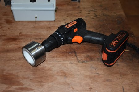
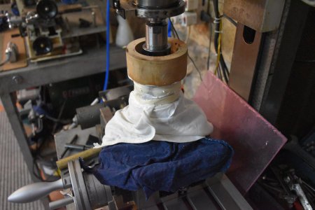
OK so the next stage is to prepare a mould to make the silicone rubber cup to drive the spinner and the drive assembly with a one way clutch to stop over speeding the drill used to power it.
The drive assembly was made first because it formed one half of the mould for the rubber cup.DSC_0083.JPG
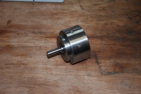
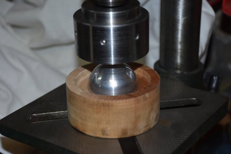
the second half was then made to match the drive and contain
the spinner to ensure a perfect fit.
DSC_0286.JPG

The mould was then filled with preconditioned silicone and the two parts mated and left to cure for 24 hrs It is important to protect all the iron and steel surfaces because the acid produced produces heavy rust.
DSC_0079.JPG
The finished drive assembly

DSC_0085.JPG
Now we are ready for the test run.
Brian.
 
For those of you who have not seen it yet this was the first run , a lot of fiddling to try and get the mixture right
so start viewing about half way.


I have run this now for about 90 minutes and here are my thoughts

1/ All my worries about vibration where unfounded the static balance has proved quite sufficient as can be seen in the video.

2/ My experiment with the carburettor is not working out so am in the process of changing to a normal slide type carb with gravity feed.

3/ The gear type oil pump delivers far to greater volume and pressure than this engine requires. The crank and mains are all ball or needle
bearings that require little lubrication as in a 2 stroke motor so this is under revision.

4/ The manifold vacuum is not good so this has to be addressed along with the carb.

5/ All though some may think this motor is finished, for me it will be the start of a long process of development I can see the possibility of fuel injection, electronic timing advance, super charging ETC, so it will keep me occupied for a while yet in between other projects,
so you can look forward to more updates , It aint finished YET.
Brian.
 
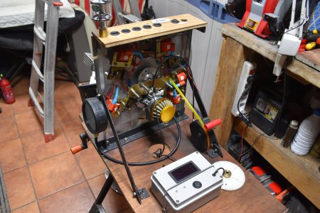
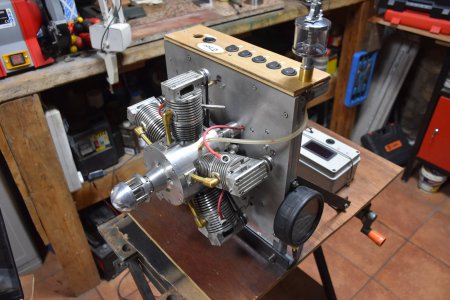
So the situation is this when the motor was running i performed a Morse test cutting each cylinder in turn and noting the RPM drop and found that No 3 was not performing well . I have reset the valve clearances because during the runs they have almost diapered not that they where big in the first place. the feed to the crank case has been replaced with a drip oiler so i can control the oil supply.
the gears in the pump have been removed for now until i make a back plate to to replace it this will be fed by another drip feed oiler
The carb has been replaced with a slide type unit mounted aft of the bulkhead. it will be fed by a gravity tank for now.
A vacuum gauge has been fitted .
Crank case and gear case drain into a common container
A small amount of oil will be added to the fuel but I am considering removing the oil control rings after the next set of tests.
I don't want to make to many changes until I have run the next tests.
Brian.

DSC_0393.JPGDSC_0394.JPG
 
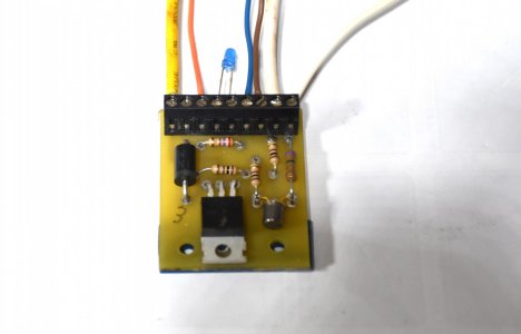
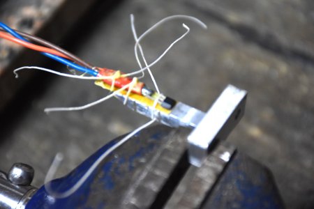
Somehow during the latest work i have managed to fry one of the ignition printed circuits so i have had to replace the power transistor
and the hall effect transistor not my favourite job but we 'got it done' as they say, A second drip feed oiler has been added to lube the gear case and a gravity fuel tank fitted. so we are nearly set up for another test just a final look at the valve and ignition timing to ensure all is OK. Then wait for a good day to have the shop doors open.

DSC_0399.JPG

DSC_0403.JPG


DSC_0406.JPG

Brian.
 
Back
Top