-
Welcome back Guest! Did you know you can mentor other members here at H-M? If not, please check out our Relaunch of Hobby Machinist Mentoring Program!
You are using an out of date browser. It may not display this or other websites correctly.
You should upgrade or use an alternative browser.
You should upgrade or use an alternative browser.
Edwards Radial 5 build thread --- PHOTOS!
- Thread starter JRaut
- Start date
Very nice mods indeed! OK I haven't thought through the gear ratio effect, so I will just ask the question. Was the intent of the adjustment slots on your ring gear more about mitigating however the 12-24 idler gear cluster happens to be soldered up? ie. the idler teeth can orient in any random position & the slots have sufficient range to clock in the cam relative to crankshaft/TDC etc? Or was the mod more about ability to tweak the engine running itself?
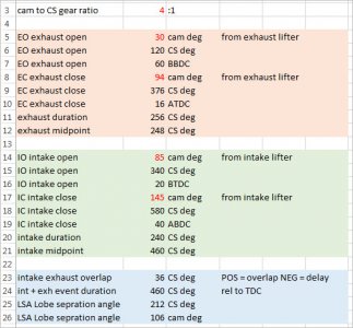
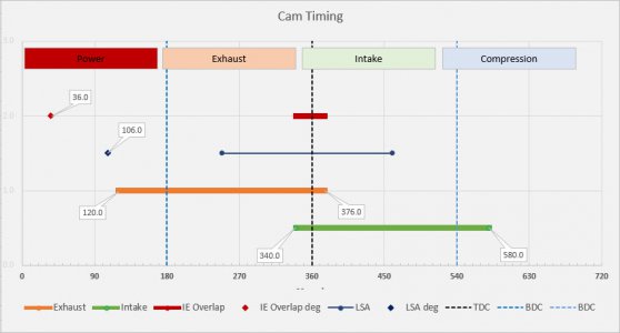
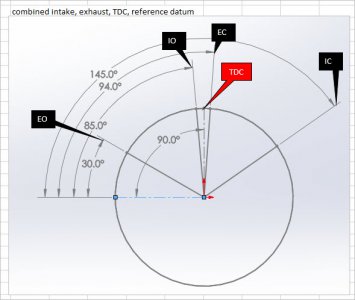
Coincidentally, I was happened to be looking at my timing spreadsheet. It evolved from me wanting to see how my radial timing compared to other engines. As you know, Edwards exhaust & inlet are of different duration (mine happen to be the same, the cam plates are identical). Kind of weird but you just don't see the typical Inlet Open at X-deg BTDC sort of numbers referenced on many designs.
It took me some head scratching to reverse engineer the cam profile, gear ratios & relative direction to come up with the answers. Timing events are also influenced by the lifter geometry (where they occur relative to the cylinder axis therefore the cam plate) so that has to be factored in. Anyways, another Edwards builder validated the numbers somewhat independently so that gave me confidence the workflow is correct. Red numbers are input values, the rest are calculated.
I then display events on a timing plot so its visually easier to see the big picture of what's going on. The point values over on the left are just for reference (in this case intake/exhaust overlap = 36 deg and Lobe Separation Angle = 106 deg). If you spot anything fishy let me know. I haven't looked at this in a while so might have to refresh my brain.
Attachments
- Joined
- Mar 9, 2018
- Messages
- 461
The main intent was so that I could get the timing set initially per the drawings. But I've at least had some thought about playing around with the valve timing by making additional cam rings, in which case having an easy way to dial in timing would be extremely beneficial.Was the intent of the adjustment slots on your ring gear more about mitigating however the 12-24 idler gear cluster happens to be soldered up? ie. the idler teeth can orient in any random position & the slots have sufficient range to clock in the cam relative to crankshaft/TDC etc? Or was the mod more about ability to tweak the engine running itself?
Regarding the 'randomly positioned idler cluster', someone over at that other thread brought up the notion that you could just assemble/disassemble/reassemble the motor with the idler gearset in each of the 18* different 'positions', and one would give you a valve timing extremely close. That's true, no doubt. But I thought my modification was a bit more elegant and robust a solution.
It now occurs to me that, even though I've built in this adjustability, it would still behoove me to make a set of timing marks on the idler gear cluster, the internal ring gear, and the gear on the crank. That way, once I get the valve timing dialed in, I don't have to repeat the process every time I pull the motor apart.
*In my earlier post I said the cluster is made up of a 12T and 24T gear. It's actually a 12T and an 18T gear; I've gone back and edited my post to fix it.
Nice looking visual you made there! Nothing jumps out at me in there as being objectionable. I made a similar spreadsheet to look at the same types of timing events and durations. But your middle plot really summarizes it nicely.Coincidentally, I was happened to be looking at my timing spreadsheet. It evolved from me wanting to see how my radial timing compared to other engines. As you know, Edwards exhaust & inlet are of different duration (mine happen to be the same, the cam plates are identical). Kind of weird but you just don't see the typical Inlet Open at X-deg BTDC sort of numbers referenced on many designs.
I've done quite a bit of work on two-stroke motors (mopeds, mostly). In the two-stroke world, valve timing is equivalent to port timing, and there's actually a surprising amount of information out in the world about timings/durations/overlaps/etc. I haven't dug into the same for 4-strokes. Certainly there must be good info out there, I just haven't looked for or see it either.
Hi JRautThe main intent was so that I could get the timing set initially per the drawings. But I've at least had some thought about playing around with the valve timing by making additional cam rings, in which case having an easy way to dial in timing would be extremely beneficial.
Regarding the 'randomly positioned idler cluster', someone over at that other thread brought up the notion that you could just assemble/disassemble/reassemble the motor with the idler gearset in each of the 18* different 'positions', and one would give you a valve timing extremely close. That's true, no doubt. But I thought my modification was a bit more elegant and robust a solution.
It now occurs to me that, even though I've built in this adjustability, it would still behoove me to make a set of timing marks on the idler gear cluster, the internal ring gear, and the gear on the crank. That way, once I get the valve timing dialed in, I don't have to repeat the process every time I pull the motor apart.
*In my earlier post I said the cluster is made up of a 12T and 24T gear. It's actually a 12T and an 18T gear; I've gone back and edited my post to fix it.
Nice looking visual you made there! Nothing jumps out at me in there as being objectionable. I made a similar spreadsheet to look at the same types of timing events and durations. But your middle plot really summarizes it nicely.
I've done quite a bit of work on two-stroke motors (mopeds, mostly). In the two-stroke world, valve timing is equivalent to port timing, and there's actually a surprising amount of information out in the world about timings/durations/overlaps/etc. I haven't dug into the same for 4-strokes. Certainly there must be good info out there, I just haven't looked for or see it either.
I have just joined as I was checking out your thread. You have really done a great job and really good account of what you have carried out so far. I have been trying to get the drawings for this engine but yahoo have delete their group engines where the drawings were stored.so I was wondering if you know where the drawing are available from now.
I am nearing the end of a 1 inch scale traction engine and looking for my next project and the engine looks just what I am looking for.
Hope you can help.
Regards
- Joined
- Apr 29, 2019
- Messages
- 2,280
I dont know about this Yahoo group, but many Yahoo groups have migrated to https://groups.io, you might search there for them.
- Joined
- Mar 9, 2018
- Messages
- 461
Thanks for following along, @Myford10, and welcome indeed!
I've been on a bit of a pause from building the radial, as other projects have crept up. They often do. I'm hoping to get back at it in the coming weeks or so.
As @Flyinfool says, many of the old Yahoo groups migrated over to groups.io, the radials group included: https://groups.io/g/RandREngines/topics
The PDF plans are still available for free download through that group. I believe you have to request to join and wait for the administrator to let you in. Let me know if you have any trouble. I hesitate to post the plans here myself, as they are not my own.
Hello everyone
Sorry not to come back sooner but I am not the greatest at these group and forum sites. But thanks to everyone for there support and help. I now have a set of drawings and will now see if I can machine these on my machines.
Thanks again for you help.
Regards
MYFORD10
Sorry not to come back sooner but I am not the greatest at these group and forum sites. But thanks to everyone for there support and help. I now have a set of drawings and will now see if I can machine these on my machines.
Thanks again for you help.
Regards
MYFORD10
- Joined
- Jan 2, 2014
- Messages
- 9,535
Sorry not to come back sooner but I am not the greatest at these group and forum sites. But thanks to everyone for there support and help. I now have a set of drawings and will now see if I can machine these on my machines.
Thanks again for you help.
Hey it's all good!
No one here expects instant replies.
If you can, we would appreciate some photos of your traction engine, and your individual take on the Edwards radial 5.
I realize that @JRaut has set some pretty high standards and would be hard to follow, but please feel free to start your own build thread here.
We would love to see it!
-brino
Hi bring
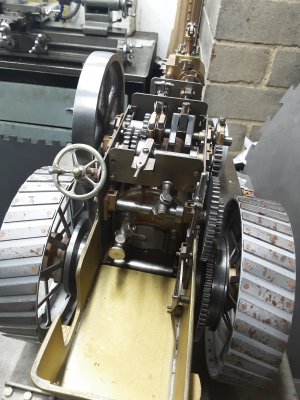
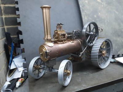
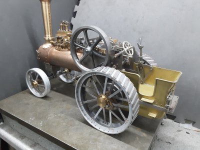
As requested a few photos of the traction engine I am building. Its a Minnie 1 inch scale by L C Mason. Been a lot of work and due to all the lockouts we have had i have getting on with it.
Regards
Myford10
As requested a few photos of the traction engine I am building. Its a Minnie 1 inch scale by L C Mason. Been a lot of work and due to all the lockouts we have had i have getting on with it.
Regards
Myford10
Attachments
Similar threads
- Replies
- 124
- Views
- 9K
- Replies
- 48
- Views
- 6K
- Replies
- 26
- Views
- 995

