Edumacate me...trying to follow your process.
Scraping- removing material- increases the ID of the assembled bearings. Given the bearings are machined to match the OD of the spindle, and you're not increasing the diameter of that part- how can you get 100% contact between bearing surfaces and spindle?
Also I’m just removing the high spots that happened from galling and running dry. I think as I scrape the bottom it falls deeper which tightens up the sides.
Also I’m just removing the high spots that happened from galling and running dry. I think as I scrape the bottom it falls deeper which tightens up the sides.
Ok got it. I had wondered whether it was galling at the beginning of the thread. I've seen them damaged at the business end of the spindle from chips getting between them.
I was lucky with mine. I completely disassembled, cleaned, painted and re-assembled after I bought it- the bearings and spindle looked new. I could barely tighten the bolts finger-tight without binding the spindle but I was told that's a good thing...
I don’t have a picture of it but it’s a gruesome homemade tool. It’s a file that I grind hole in the middle on a belt sander and sharpened the edges. It’s supposed to mimic a spoon scraper. You make it rainbow shaped and put the ends of the rainbows on the surface to be scraped. I made it very poorly and I’m sure the wrong dimensions but it’s working for me and this is probably the only time I’ll need it. :knock on wood:
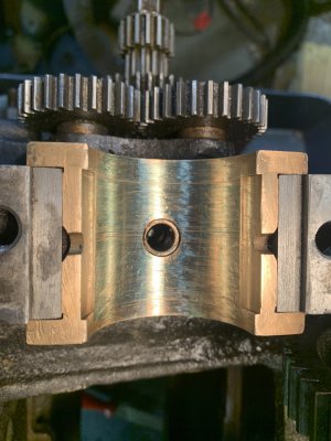
Here’s a picture of the front bearing cap before I scraped it
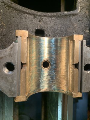
Here’s after.
I still need to keep working, it’s not as good as the second picture looks. I put the blue on a little too thick. The next time I checked it had less coverage but still probably at least 75%. I can still clamp the spindle when tightening it so I might keep going a smidge more.
That doesn’t look bad, don’t let perfect be the enemy of good. Can always take off more but putting it back on is much harder.
You won’t be looking at this surface, and the spindle should be much harder than the bearing. I’d put it back together and see how it runs.
My old Seneca Falls Star had bearings that looked worse than that and it ran fine. Remember, it should really be running on a film of oil, not really metal on metal.
The issue that appears to of happened was that the bearings were so egg shaped that I was contacting metal on metal on the sides but still very loose up and down. I am going to see how it does now. The front bearing feels gray with .001 of deflection. The rear starts to snug a little with .001” of defection. I’m going to fool with torquing it less and see. Worst case I will work on that one some more. I think it’s still pinching the sides of the spindle. It’s really close though.
I've never quite grasped the spatial relationship between bearings and spindle as to why torque on the caps should matter (I know it does, just don't understand the geometry).
In theory I thought both spindle and bearings represent concentric circles, with the bearings being the larger "circle" by whatever clearance is desired. Obviously that isn't the case or we'd just tighten the bearing caps (torque would be irrelevant, within reason at metal-on-metal) and have the designed clearance.
So how was the geometry for plain bearings designed for these parts new from the factory?
I think when you are taking.001” clearance it all matters. I mean if it floats on the oil the oil is 0.0005” thick. Over torquing the caps can distort stuff even the smallest bit. My understanding about this lathe from reading around, the bearing would of been fitted and the cap mounting surface would of been scraped to fit the machine also.
Well so far I’m super happy. After all that work fitting the bearings. I went from 4-7 thou of slop to .0012 on the front and .002 on the rear. I ran it at the highest speed for 10 minutes and the bearings went from 45*F to 77*F. I will keep an eye on it but after 10 minutes the spindle turned freely like nothing was binding up. I will have to recheck the clearances after running some more.
This site uses cookies to help personalise content, tailor your experience and to keep you logged in if you register.
By continuing to use this site, you are consenting to our use of cookies.