THAT'S the evidence I'm talking about before chucking parts...
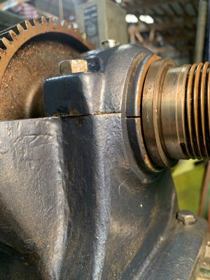
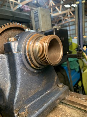
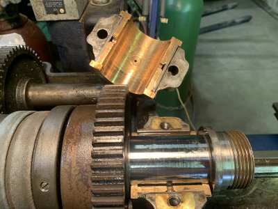
That indeed does look like it's bound up during it's lifetime. It's hard to tell in the pictures, but looks pretty smooth. If there's evidence otherwise, like dings, scratches, gouges, or metal that's "picked up" from one side to another, that's going to need to be addressed. But that looks to me like it got set up and run too tight at "some" point in it's life. And with that much wear, and still tightening up for you when it's run too fast, without picking up much if any metal transfer- That's painting a picture
Wear like that (Assuming I'm right from the images and there's not metal transfer going on) can be run just fine, you'll have to pay attention for that with first hand eyeballs. The high spots and the low spots are matched though, which means the bearings HAVE TO stay in the same place and orientation. They're matched at this point with the asymmetrical wear pattern.
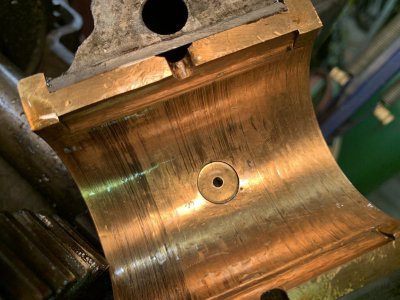
That surface is going to make it basicaly not possible to measure an actual useful clearance by standard methods. My recommendation would be to start with a coarse and simple test, and simply use a strip of plastigauge. If you can get a green one, that's great, but usually the cheapest way to get it is at a local parts store (four to ten bucks is typical), and they'll have a kit of all three. For something that cheap on the internet, the price gets jacked to cover the shipping (or you're paying shipping), so often the local kit is easiest/cheapest.
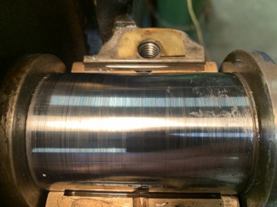
These are not "perfect", they're not precision go/no go gauges, and there's usually half a thousandth of an inch worth of uncertainty left on the table for a one thousandth strip, but what that can do is this- It'll follow the contours, it'll measure consistantly, if not dead accurately, across the whole string. It'll reflect the actual clearance through all of the grooves so even if the measurement's off half of a thousandth, you'll know "around" some amount, and you'll know if it's consistent, or has really tight spots. And generally tell the story for you of how this is going together, and if those two worn surfaces are capable of playing nice together.
Given the damage I see, that's the cheapest, easiest, fastest way to qualify/quantify where you're at and point you in the best direction to go in, be that working with the spindle/ bearings you have to make them servicable, and/or trying to match,fit, qualify, verify a used set that is (pretty likely since it's old, not yours and it's used) going to be well worn in to a different lathe, with different tolerances on the machining, etc. (That'll be nice to have the plastigauge for that too, it'll help you get where you need to be far easier than dialing in new/used split bushings from scratch, although that is certainly doable as well). Each option has their own up sides and down sides, and knowing where you're headed will get you going in the right direction for the best possible outcome.