Beauty in The Beast: Webb 5BVK Barn Find/Conversion

That table is beautiful, not too often you find an old machine with a table that looks that good. Looks really good sitting in your shop, looks like it belongs there.
Thank you! I went at the knee with brute force - but I tackled the table with some care using some learned skills from the two stroke world. It was such a pleasure to see it come to life like that.

That probably is the "spindle drive"
Let's see some pictures of the electric cabinet.
Some prior discussion on electronics occurred - I'm reposting below so its all in one place.
This is a week area for me (some reading this now are thinking - THATS NOT THE ONLY AREA!)

But before I get to that, might be helpful to refocus the general plan/ reasoning.
- Would like to have manual control. For my quick jobs in future - and I just plane like the idea of moving it manually
- *I see value in getting up and running quickly. Doesn't have to be pretty or full function. Keeps my momentum and starts building experience. Not to be underestimated.
- Have read a bit about the issue of ball screws being "too" easy to turn for manual. Assumed some form of table lock could help if needed.

Phase I - get it operational manually. Im ok with belts and cogs being exposed. Doesn't have to be pretty. Drill can be my power axis operation.
Phase II - CNC - with lower profile electronics. Volume of electronics seems enormous currently. Would like a lower profile solution.

Ok - now on to some specifics.
I'm going to order the DRO and a VFD - if I need it.
Not sure I do??
As far as the VFD, it looks like it is sized properly to run with the spindle motor on a 240V single phase supply.

The VFD has three conduits coming out of it. 2 go to the cabinet. 1 goes directly to the spindle motor...
Of the two that go in to the cabinet
- one has what appear to be low voltage wires that go to the main terminal strip (7) in pic below.
- The other has 4 heavy gauge red wires that go to the main disconnect and fuses - one to each. This appears to me to be the power source for the VFD.
IMG_2405.JPG
IMG_2400.jpg

Ok - let's revisit the path to phase I - 'cause I am now kinda lost.
Goal here is to have a workable manual mill.
Can be a little redneck out of the gate. I don't mind refining after I have operated a bit and understand it better.
So either nice handles I add - or I just turn the exposed cogs by hand or with drill (have been doing so for past few days).
Reasonably priced off shore DRO gives me my coordinates, plugs in to a 110 outlet on my wall.
Do we think this VFD could just be wired to have a 220 plug and... plug in giving me spindle power?
(I will need a handle for the quill lowering).

Secondarily - is there a means for me to test my servos with a bench power supply? I posted a pic above showing the tag on them for specs. I couldn't really make heads or tails of it.


That probably is the "spindle drive"
Let's see some pictures of the electric cabinet.
Ok - re-posted from elsewhere - with a few extra's thrown in for your viewing pleasure.
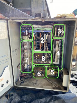
Basic components are circled. I did that so I could get help identifying what's what.
Writing in red was from later posts that discussed what some components might be.
Below should be seen as general overview - to be confirmed.

#1 Reversing contactor for spindle motor. Remove, not needed. Has been replaced by the VFD
#2 Servo Drives. Keep, needs some slight modification to run on 120VAC single phase. I'll explain the 120VAC later
#3 Main disconnect & fuses. Keep
#4 Supplementary protection (fuses). Keep
#5 240/120 VAC Control Transformer. Keep.
(It was also proposed that it might be the servo drive transformer." I think that huge toroid feeds AC through the two black wires to #8, where it's rectified and smoothed with what looks like a gigantic cap to the right of the brown box. That transformer must weigh 40lbs.")
#5A Small contactor. Coolant pump relay?
#6 Servo drive power transformer. Remove, not needed.
(Some question on what this was)
#7 Terminal strip. Keep, always useful.
#7A Small transformer at bottom. Not sure what it's for, need further information.
(It was also proposed this might be the 120vac control transformer.)
#8 Ice cube relays. May be useful, depends on coil voltage.
#8A DC Power supply section for servo drives (behind the brown panel). See #2 above

IMG_1770 2-2.JPG

Back of control panel:
IMG_2398.JPG

Door of control panel when open:IMG_2397.JPG

main box better pics:IMG_2399.JPG

IMG_2401.JPG
 

Attachments

  • IMG_1770 2-2.JPG
    IMG_1770 2-2.JPG
    4 MB · Views: 5
Thank you! I went at the knee with brute force - but I tackled the table with some care using some learned skills from the two stroke world. It was such a pleasure to see it come to life like that.


Some prior discussion on electronics occurred - I'm reposting below so its all in one place.
This is a week area for me (some reading this now are thinking - THATS NOT THE ONLY AREA!)

But before I get to that, might be helpful to refocus the general plan/ reasoning.
- Would like to have manual control. For my quick jobs in future - and I just plane like the idea of moving it manually
- *I see value in getting up and running quickly. Doesn't have to be pretty or full function. Keeps my momentum and starts building experience. Not to be underestimated.
- Have read a bit about the issue of ball screws being "too" easy to turn for manual. Assumed some form of table lock could help if needed.

Phase I - get it operational manually. Im ok with belts and cogs being exposed. Doesn't have to be pretty. Drill can be my power axis operation.
Phase II - CNC - with lower profile electronics. Volume of electronics seems enormous currently. Would like a lower profile solution.

Ok - now on to some specifics.
I'm going to order the DRO and a VFD - if I need it.
Not sure I do??
Let's get a picture of the data plate on the spindle motor, then a decision can be made on the VFD

The VFD has three conduits coming out of it. 2 go to the cabinet. 1 goes directly to the spindle motor...
Of the two that go in to the cabinet
- one has what appear to be low voltage wires that go to the main terminal strip (7) in pic below.
- The other has 4 heavy gauge red wires that go to the main disconnect and fuses - one to each. This appears to me to be the power source for the VFD.
It looks like the VFD was wired for 3 phase input.

Ok - let's revisit the path to phase I - 'cause I am now kinda lost.
Goal here is to have a workable manual mill.
Can be a little redneck out of the gate. I don't mind refining after I have operated a bit and understand it better.
So either nice handles I add - or I just turn the exposed cogs by hand or with drill (have been doing so for past few days).
Reasonably priced off shore DRO gives me my coordinates, plugs in to a 110 outlet on my wall.
Do we think this VFD could just be wired to have a 220 plug and... plug in giving me spindle power?
(I will need a handle for the quill lowering).
Maybe the VFD will work on 240 single phase. Really need to see the specs on the spindle motor and I'll try to find the manual for the VFD.
Secondarily - is there a means for me to test my servos with a bench power supply? I posted a pic above showing the tag on them for specs. I couldn't really make heads or tails of it.
A 12V battery would be perfect to see if the motors will turn. I would guess at 12V they will turn about 100 or so RPM. Just disconnect armature wires and connect to a battery.
 
Ok - I did the best I could with both.
Labels are worn.
My owner's manual - general - says: 50Hz/60Hz 3 phase 220-575V (as specified on order)
It is a 5 HP.
VFD appears to my eye to be a 502 3A7. the manual I posted above seams to align with that.
I opened the cover so I could see how they had the jumpers wired - picture of that also below.
Motor - best I can make out:
Type = M
INS CL = L or E
Rotor = C
Code = ?

One crystal clear marking - its stamped - on motor place: Amp = 14
Hz = 60
Volt = ?20 (looks like 220 to me)

Tried a couple angles to rid reflection.
So scratched - see what you think.IMG_2414 2.JPGIMG_2416 2.JPGIMG_2417.JPGIMG_2427 2.jpgIMG_2428 2.JPG
 
OK, that's not the same VFD that is in the eBay link. That one is a 7A5 which is a 10HP unit. You are not going to be able to use the 3A7 one to run that 5HP motor on single phase. The HUANYANG GT that you linked to will work on single phase.
 
Got it.
(Hadn't initially realized that AF500 wasn't the actual model name)
Thanks for helping double check.
Will order the Huanyang GT.

I can test the servos with my bench power supply - it's adjustable for both volt and amp and goes 0-24V I think.
The servos all have two sets of wires going in.
Have been wondering about this.

Assume the lower set of input wires power the servo to spin.
Perhaps the upper is some sort of feedback sensor for RPM ?

There is also some form of "micro switch" who's wiring runs through the same conduit as the servos.
This appears to have told the machine something about positioning.

Thanks.
See below.

Here is a picture of the spindle servo.IMG_2364.JPG

The lower box can be seen here - open: (the two wires exiting appear to supply power to an ancillary component)IMG_2439.JPG

And here is a little diagram in the back of the box cover:
Can you help me with where I would apply the 12V pos and negative to test?IMG_2438 2.JPG

There are two of these - one on the X and one on the Y - which run back to the servos - and then I suspect are home runned back to the central box. These I assume are limiting switches of some kind - and may or may not have a future on my set up?

IMG_2440 2.JPG
 
The A1 and A2 wires are the wires that you would want to connect the 12V to. But on the Z motor you have 1 more problem, it seems to have a brake, BR1 and BR2. Most likely24VDC. I'm assuming that the blue wires are the brake wires, energize to release. There may be some brake information on the motor data plate.

Now, what I have never seen before is the 2A1 and 2A2 connection. Given that there is a shielded cable going to that connection, I'm going to make a best guess that 2A1 and 2A2 is the tach connection back to the drive.

Yes, the limit switches will be in your future.
 
Since you are going for the manual option to start with, you are going to need a way of manually controling the VFD

Here is what I did on my mill. I made this control box.
1622655571911.png

Then mounted it on the front of the head, you may want to mount in a different place, it really doesn't matter. I was able to mount it here because I converted mine to direct drive and removed all of the mechanical variable speed hardware. I can switch this over to computer control by flipping a switch on the control cabinet.
1622655782303.png

Parts list from Automation Direct https://www.automationdirect.com/adc/home/home

ECX2300-5K
AutomationDirect potentiometer, 5k ohm, 22mm, black.

SA110-40SL
AutomationDirect pushbutton enclosure, 4 holes, 22mm, 185 x 70 x

GCX1131
AutomationDirect emergency stop pushbutton, 22mm, twist-to-releas.

GCX1102
AutomationDirect pushbutton, 22mm, momentary, (1) N.O. contact(s)...

GCX1300
AutomationDirect selector switch, 22mm, 2-position, maintained,

E22NS31
Eaton legend plate, aluminum, rectangular, black field, silver ba.

E22NS34
Eaton legend plate, aluminum, rectangular, red field, silver back..

E22NS38
Eaton legend plate, aluminum, rectangular, black field, silver ba..

ECX2640
AutomationDirect legend plate, plastic, square, black field, blac.
 
Last edited:
Jim - you're a star!
Thanks for thinking forward on that one and listing.
Looks like a few of those components are out of stock... such is life.
Plenty of other options though - but I want to make sure I am focused on the right specs.

Have been thinking about this - considering two places to put it.
See pic below.
Was thinking I might be able to use that front panel as my spot.
If not - then just to the right of it.

Question: If I maintain the mechanical variable speed controller could I utilize just two switches to do the job?
- Emergency stop
- On/off/On rotary selector (assuming one exists)

If yes - would the On/off/On require 2 N.O positions?
(I was confused by the spec for the switch you noted above for reverse and forward as it has only 1 N.O. connection listed. I may not be understanding how I would be wiring it though)

Amazon sells these:
https://www.amazon.com/gp/product/B07WTL3KPB/ref=crt_ewc_img_srh_3?ie=UTF8&psc=1&smid=A135XTKU400AZ0
&
https://www.amazon.com/TWTADE-2Pcs-...ary+switch&qid=1622670110&s=industrial&sr=1-1

I kind of like the shinny red stop button.
If I need a third button for power on/off, I've spotted these:
https://www.amazon.com/gp/product/B..._title_dp_2?ie=UTF8&psc=1&smid=A1POY47GM797OI
IMG_2449.JPG

Tough to know if there is enough space - but maybe.

IMG_2450.JPG
 
Back
Top