Accurately measuring and boring holes (28mm)

Perhaps i used the wrong term. Snap gauges.

28mm is larger than an inch, and my telescoping/ snap gauge set has smaller than an inch, so i think it would be covered. Perhaps the storage of the set is in question.

Sent from my SM-G970U using Tapatalk


Oh boy, now you dunnit.

Call them what you like, but his bore is only 8mm deep. Not a good application for these.
 
Do you think it would be a good idea to clean/repair the "torque thing" in case that might return the subject micrometer to fit-for-purpose condition?
I was taught from the beginning to go by and develop the proper feel and forgo the ratchet/friction thimble.

Reason being that clean/dirty, this/that style will all act differently.
 
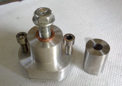
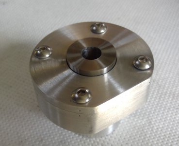
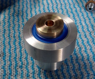
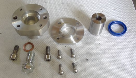
This clutch slave cylinder was made in my workshop, 6061 ally with a 22mm bore, the piston is 22mm and is a neat sliding fit inside the bore. I used a vernier gauge caliper for sizing the bore and a micrometer for the piston. The end cap is a press fit, .05mm, as is the seal.

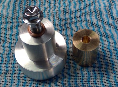
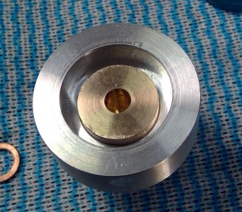
The second slave was also made in my workshop, it is 6061 and the piston is phosphor bronze. I used the same procedure. As both have a recess at the front for the seal my internal micrometer did not reach far enough down to measure, hence the vernier.

To check sizes I generally measure something with the vernier and the micrometer to make sure they are giving the same readings.

I also tried the piston in the bore at various stages to make sure I didn't overshoot the sizings.
 

Attachments

  • WIN_20240303_11_36_25_Pro.jpg
    WIN_20240303_11_36_25_Pro.jpg
    750.7 KB · Views: 8
  • WIN_20240303_11_19_45_Pro.jpg
    WIN_20240303_11_19_45_Pro.jpg
    416.5 KB · Views: 8
  • WIN_20240303_11_15_24_Pro.jpg
    WIN_20240303_11_15_24_Pro.jpg
    305 KB · Views: 7
  • WIN_20230117_15_45_26_Pro.jpg
    WIN_20230117_15_45_26_Pro.jpg
    504.6 KB · Views: 7
  • WIN_20230117_15_51_35_Pro.jpg
    WIN_20230117_15_51_35_Pro.jpg
    377.6 KB · Views: 6
  • WIN_20230117_15_55_26_Pro.jpg
    WIN_20230117_15_55_26_Pro.jpg
    466.3 KB · Views: 6
Ischgl99: Cheap import bearings which could be why they're so far off. I like to keep an assortment of "cheap stuff" around for the odd non-vital jobs but it can definitely throw you off track sometimes.. I don't trust my 27.9 measurement entirely but it should be within +/- 0.03 when comparing to standards and my other measuring equipment.

David2011: That's what it intuitively felt like to me as well. I could apply much more torque than I was comfortable with before it slipped, at least on my two internal mics which are cheap imports. The The ratchet knob is much softer on the external digital mic and it feels much more "appropriate". I need to see if I can disassemble and service the cheap imports, maybe fix some of the calibration and stiffness issues..

Huub buis: That's a lot of great info, thanks!

What I've done for these last practice pieces is start with a 50mm round stock, drill to 19mm and then start boring to 25.00mm in 0.5mm steps.
Since the machine is a "manual-converted-to-CNC" I've also been experimenting with automating it more.
The first two pieces I measured after every 0.5mm pass to dial in both feeds/speeds and actual diameter I was getting, being careful with temperature too.
The following parts I tried running an entire program, taking it from 19 to 24.5 and then measuring/adjusting program and only doing the final pass to 25.00 separately.
This amount of material removal of course tended to heat up the part quite a bit so I aimed for ~25.03(hot) which seemed to result in a tight sliding fit once cooled down, possibly not the best method but I'm impatient. :grin:
The pieces are 21mm thick and with the shaft of a 25mm end mill slid through, you can just barely feel the sideways movement.
To the best of my abilities the end mill seems to be around 24.9 to 24.94 ish so the hole itself should be very close to 25.00.

I think if I measure the sideways deflection a certain distance away from the hole and more accurately measure the end mill shank, I should be able to quite accurately calculate the bore size with trigonometry, could be an interesting experiment and give me something to "aim for" when testing the other measuring tools.
You may be onto something when mentioning the”cheap import bearings”. Some years ago I purchased a 10,000 lb. capacity trailer to haul around my tractor and end loader. I was informed at the time of purchase that it would probably need wheel bearings

I didn’t want to spend much time looking around so I ordered some from E Trailer. I noticed when they came they were made off shore. They didn’t last 3 month of light use. They overheated and galled. I changed them out for quality US made bearings and have never had another problem
 
Perhaps i used the wrong term. Snap gauges.

28mm is larger than an inch, and my telescoping/ snap gauge set has smaller than an inch, so i think it would be covered. Perhaps the storage of the set is in question.

Sent from my SM-G970U using Tapatalk
An internet search for “telescoping gauges“ turned up the items also known as snap gauges including Starrett telescoping bore gauges at McMaster Carr. That’s what I’ve always called them as well.

MrCrankyface, the method that I use to make flat bottomed bores may not be a normal practice but it works. For holes around 1”/25mm bore I drill a starting hole about 5/8”/16mm, stopping short of the desired depth. Then I plunge a center cutting end mill into the hole to just short of full depth. At that point I open the hole with a boring bar to just short of the final diameter. Finally the end mill is used again to bring the hole to full depth and the boring bar is used to cut the full diameter. The reason I go back and forth between the cutting tools is that I’m not a professional and this method reduces the number of touch-offs so the bottom of the hole is smooth when finished.
 
BTW - This is a great place to use a carriage stop.
 
An internet search for “telescoping gauges“ turned up the items also known as snap gauges including Starrett telescoping bore gauges at McMaster Carr. That’s what I’ve always called them as well.

MrCrankyface, the method that I use to make flat bottomed bores may not be a normal practice but it works. For holes around 1”/25mm bore I drill a starting hole about 5/8”/16mm, stopping short of the desired depth. Then I plunge a center cutting end mill into the hole to just short of full depth. At that point I open the hole with a boring bar to just short of the final diameter. Finally the end mill is used again to bring the hole to full depth and the boring bar is used to cut the full diameter. The reason I go back and forth between the cutting tools is that I’m not a professional and this method reduces the number of touch-offs so the bottom of the hole is smooth when finished.
A less labor intense method with even lass touch offs is to get near your size/depth and use a boring bar insert/cutter that can both bore and face in one setup.

Go in to your rough bore and find your depth to within .005-.010 and step this depth out until you're at your rough bore dimension, then bring the bore to finished size and use the cross slide to walk the boring bar inwards to finish the bottom of your bore.

Obviously using your carriage stop as a function of this.
 
RBW, that sounds like a good process. I’m mostly self taught beyond what it takes to rebarrel a rifle so much of how it gets done is figuring out “how to“ with the tools on hand. Been thinking that I need some smaller boring bars and this confirms it.
 
So some lessons learnt if it helps someone else:
-Experience helps a lot. I'm getting a lot more repeatable and reliable measurements after having experimented with my different equipment over several days. Just small things like knowing my 25-50mm internal mic needs very specific handling and also shows ~15 microns too much.
-Sharp cutters makes life much easier. I had some trouble with boring bars and ended up making one from HSS, this ended up being very forgiving and easy cutting hence making it easier to get accurate dimensions and cylindrical holes instead of a cone.
-Don't assume your measuring equipment is measuring correctly, compare to standards, parallels etc to get an idea of what it's actually showing.
-Especially with telescoping gauges, make sure the surface finish is good and measure several times so you know if you're getting repeatable values. I found with rough surfaces and/or burrs I would get very random measurements.
-In general it helps to stop before nominal dimension and take even cuts down to final size. Ie stop 1mm before final dimension and start taking 0.2mm cuts, measure between each cut to see how you're doing and adjust the next cut. This would over and over produce very accurate dimensions.
 
Back
Top