2020 POTD Thread Archive

3D printed ER32 collet holder and collets for tool and cutter grinder build. Includes square and hex collets.
7894ebfe924410e67edc5d0567a8fa7f.jpg
Im just not that sold on anything 3D printed which is supposed to be precision. Maybe Im wrong...But the threading dial I purchased for my South Bend lathe was pure garbage. After less than 1 Month...The Gear was falling apart. I couldn't keep the set screw tight. And in the end..The only use I had for it was as a pattern to make an aluminum bodied threat dial. And I used the gear as a paternities for a delrin gear.

So...Im not trying to be ugly here as I don't like to discourage anyone who tries a project and does said project. Plus...It looks like you've made a good looking part. But...How can a printed collet stand up to repeated use and continue to give repeatability within a 1/2 thousandth. If it works good for you and serves your need...Great. But from the outside looking in...and with my limited experience with 3-D printed items...I question this sort of tool from a 3d printer.
one suggestion I will give is this. Maybe make you collet undersized. Drill and then ream to size. At least then you will be on time with a collet similar to an emergency collet. but.....it just may not hold up over time.
 
Last edited:
Decided to build a 6 x 6 sine plate with no immediate need for one.
The plates are 1inch hot roll, the hinge and anvil? are hardened and ground shaft.
Got the plates within a 1/2 thou of square, the rolls within a 1/2 thou of 5 inches spacing, and the top within 2 tenths of flat.
Still need to make side plates and a tie down strap.
That’s an interesting design for a sine plate that I have not seen before, especially the nest for the “stationary” round. What is the computation for height for a desired angle? It seems to me that the nominally 5” hypotenuse would change a bit as the angle varies, and would be more complex than simply H=5” x sin A. Please explain?
 
That’s an interesting design for a sine plate that I have not seen before, especially the nest for the “stationary” round. What is the computation for height for a desired angle? It seems to me that the nominally 5” hypotenuse would change a bit as the angle varies, and would be more complex than simply H=5” x sin A. Please explain?
Thought I was following the normal design. The top plate nests the two rounds 5 inches apart for the hypotenuse. The bottom plate is relieved to bring the surface to the height of the bottom of the hinge. ie no spacer 0 degrees for the top plate

Greg
 
F360ca, I see, I misunderstood. I see that the height of the tangent point of a plane on the fixed round does not change as the table tilts.
Disregard, sorry.
 
refurbed a couple of Gerber multitools I found so I could give them to my daughters for their birthdays (Friday and today). The newer one turned into quite the project as it was missing the locking pins and clips for the slide out plier, was bent (must have been runover a few times) and had 2 broken blades and a broken saw. The older one was a piece of cake in comparison and needed only a new blade.
View attachment 321573

locking pins and clips, made from stainless of some description. Man they look like ar$e close up!
View attachment 321574View attachment 321575View attachment 321576

all in place
View attachment 321578

made some blades out of 7/64" O1 that was milled down to the necessary thickness, then filed/ angle ground to shape before torch hardening and quench in ATF. Here they are after a nice cook at 400F or so for an hour.
View attachment 321577

sharpened and cleaned up (a bit)
View attachment 321579

old one
View attachment 321580
new one. The saw blade was fixed by carefully grinding a slot down the centerline of the broken piece, then pinning and JB welding in a piece of hacksaw blade.
View attachment 321581

the girls were happy and I had many happy hours distracting myself in the garage. Plus I think I'm actually starting to get a handle on the whole hardening O1 thing..
If you send them to Gerber the will send you new ones...lifetime warranty

Sent from my SAMSUNG-SM-G930A using Tapatalk
 
I don't know if I have shown this before? This is a good tip/trick.
1587996161151.png

You all know how hard it is to lock down the swivel with the puny 3" arms on the screws that come with the vise. Cut them off and machine the end of a bar to fit the hole in the screw. This gives much more leverage and then slides out to store just behind the vise so it is not in the way.
A really clever machinist might design and employ a holder for the bar as well.
Robert
 
POTD was doing some work on the starter of our Massey Ferguson 35 farm tractor. The starter has a ratcheting bendix that shoots out to engage the engine flywheel. It spins back into the "home" position once power is removed. Problem was, the bendix was stuck in the extended position so the starter was always engaged with the flywheel.

I now have another reason to love the internet. Google'd "starter bendix stuck out" and a 2 minute YouTube video from Steiner Tractors showed up. The bendix is held to the starter armature shaft with a roll pin. Tapped that out and spun the bendix back using a slight mod of Steiner's video. Their video has the bendix riding a screwdriver, then set the outside of the bendix to a spinning bench grinder with a wire wheel. Let it get up to smokin' hot speed, and push the base toward the gear. They use their hand on the base of the bendix, I used a steel round with a through hole.

I figured if the bendix over-traveled and stuck once, it'd do it again. Made a bushing on the lathe to act as a stop to limit travel of the bendix so it can't over-travel and get stuck again. I used brass which may not hold up, so may end up having to remake it in stainless or something similar. Yes, it reduces the amount of gear engagement to the flywheel. I measured the engagement at about 0.45", so hoping that'll be enough engagement.

Thanks for looking, Bruce


Bendix in the starter is stuck in the fully-extended position. Easy to hear when this happens and the tractor is running!
20200426_152635.jpg

Bendix attaches to the starter armature shaft with a roll pin. The housing on the right with the pinion gear should rotate back on the helical gear to the base. Problem is, it's stuck fully extended.
20200426_153012.jpg

Gotta love YouTube! Found a video from Steiner Tractors for fixing a stuck Bendix. Ran a screwdriver through the shaft that extends into the steel round on the right. Used a bench grinder with a Scotch-brite wheel and got the Bendix spinning. Then squeezed with the screwdriver and round to get the Bendix to fully retract.
20200426_153100.jpg20200426_153202.jpg

Bendix back on the armature. VERY carefully extended the pinion on the helix until the roll pin hole was just exposed.
20200426_153418.jpg20200426_153425.jpg

Made a stop-bushing/thrust washer to limit the travel of the Bendix. Basically measured the gap between the end of the pinion to the housing of the starter. Started to extend the pinion until it stuck. Figured a bushing 0.080" short of that number would work.
20200426_160413.jpg

Simple lathe job from there. Chucked up some 3/4" brass (jury is still out on my choice of materials), faced, center drilled, drilled a clearance hole, bored both ID's and parted.
20200426_154733.jpg20200426_155244.jpg
20200426_155401.jpg20200426_160139.jpg
20200426_160612.jpg20200426_160952.jpg
20200426_161146.jpg

Decided on the OD by measuring the distance across the bottom of the teeth on the starter pinion gear. Figured the flywheel teeth couldn't extend past there. Measured about 0.830", so went with a 0.75" OD bushing.
20200426_161327.jpg


Dry fit the bushing in place and extended the Bendix. Didn't come out far enough to stick.
20200426_161421.jpg20200426_161428.jpg


Measured 2.030" from the face of the starter flange to the flywheel gear on the tractor. Measured 1.900" on the starter, so in the retracted position there's about an 1/8" clearance between the Bendix and the flywheel gear. The Bendix gets about 0.60" of travel with the bushing in place, so getting about 7/16" of gear tooth engagement.
20200426_162404.jpg20200426_163222.jpg


Success! Works great though I'll pull the starter after the summer and see how the brass is holding up.
20200427_085742.jpg
 
POTD was doing some work on the starter of our Massey Ferguson 35 farm tractor. The starter has a ratcheting bendix that shoots out to engage the engine flywheel. It spins back into the "home" position once power is removed. Problem was, the bendix was stuck in the extended position so the starter was always engaged with the flywheel.

I now have another reason to love the internet. Google'd "starter bendix stuck out" and a 2 minute YouTube video from Steiner Tractors showed up. The bendix is held to the starter armature shaft with a roll pin. Tapped that out and spun the bendix back using a slight mod of Steiner's video. Their video has the bendix riding a screwdriver, then set the outside of the bendix to a spinning bench grinder with a wire wheel. Let it get up to smokin' hot speed, and push the base toward the gear. They use their hand on the base of the bendix, I used a steel round with a through hole.

I figured if the bendix over-traveled and stuck once, it'd do it again. Made a bushing on the lathe to act as a stop to limit travel of the bendix so it can't over-travel and get stuck again. I used brass which may not hold up, so may end up having to remake it in stainless or something similar. Yes, it reduces the amount of gear engagement to the flywheel. I measured the engagement at about 0.45", so hoping that'll be enough engagement.

Thanks for looking, Bruce


Bendix in the starter is stuck in the fully-extended position. Easy to hear when this happens and the tractor is running!
View attachment 322358

Bendix attaches to the starter armature shaft with a roll pin. The housing on the right with the pinion gear should rotate back on the helical gear to the base. Problem is, it's stuck fully extended.
View attachment 322359

Gotta love YouTube! Found a video from Steiner Tractors for fixing a stuck Bendix. Ran a screwdriver through the shaft that extends into the steel round on the right. Used a bench grinder with a Scotch-brite wheel and got the Bendix spinning. Then squeezed with the screwdriver and round to get the Bendix to fully retract.
View attachment 322360View attachment 322361

Bendix back on the armature. VERY carefully extended the pinion on the helix until the roll pin hole was just exposed.
View attachment 322362View attachment 322363

Made a stop-bushing/thrust washer to limit the travel of the Bendix. Basically measured the gap between the end of the pinion to the housing of the starter. Started to extend the pinion until it stuck. Figured a bushing 0.080" short of that number would work.
View attachment 322364

Simple lathe job from there. Chucked up some 3/4" brass (jury is still out on my choice of materials), faced, center drilled, drilled a clearance hole, bored both ID's and parted.
View attachment 322365View attachment 322366
View attachment 322367View attachment 322368
View attachment 322369View attachment 322370
View attachment 322371

Decided on the OD by measuring the distance across the bottom of the teeth on the starter pinion gear. Figured the flywheel teeth couldn't extend past there. Measured about 0.830", so went with a 0.75" OD bushing.
View attachment 322372


Dry fit the bushing in place and extended the Bendix. Didn't come out far enough to stick.
View attachment 322373View attachment 322374


Measured 2.030" from the face of the starter flange to the flywheel gear on the tractor. Measured 1.900" on the starter, so in the retracted position there's about an 1/8" clearance between the Bendix and the flywheel gear. The Bendix gets about 0.60" of travel with the bushing in place, so getting about 7/16" of gear tooth engagement.
View attachment 322375View attachment 322376


Success! Works great though I'll pull the starter after the summer and see how the brass is holding up.
View attachment 322377
Nice repair. I just love well made old stuff that’s actually serviceable. Thanks for posting.
 
If you send them to Gerber the will send you new ones...lifetime warranty

Sent from my SAMSUNG-SM-G930A using Tapatalk

even if I found them on the side of the road?

Oh well, bit late now, but I'll check that out if I find any more.
 
Perhaps a submission for the most overkill and cost ineffective use of the equipment in the shop. A few thousand dollars worth of machines, tooling and material which can make almost anything up to a certain size (not real big, I largely try to make model steam engines. But I am not angry or disappointed.
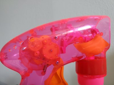
This, of course, involves grandaughters. Gunsmiths, take note - the bubble making squeeze gun locked up. Failure to fire. This reduces the number of unicorn and rainbow moments to an unacceptable level. The small stub shaft of the gear driven by the curved rack on the trigger sheared off due to what I believe to be extreme enjoyment. While I should have used stainless, the rest of the life of this toy and rather generous tolerances on a 2mm nominal shaft, I turned down an 0.093 steel rod and drilled an appropriate hole in the gear, removing all of the old shaft. This will likely wear out the exquisite molded bearings. it is on the larger gear visible near the middle of the bubble-arm. They are now ready to defend their princess castle.
 

Attachments

  • 20200427_125647.jpg
    20200427_125647.jpg
    2.7 MB · Views: 50
Back
Top