Who knows about simple electronics?

Inferno

Registered
Registered
Joined
Feb 24, 2019
Messages
927
For whatever reason I can never wrap my head around diodes.
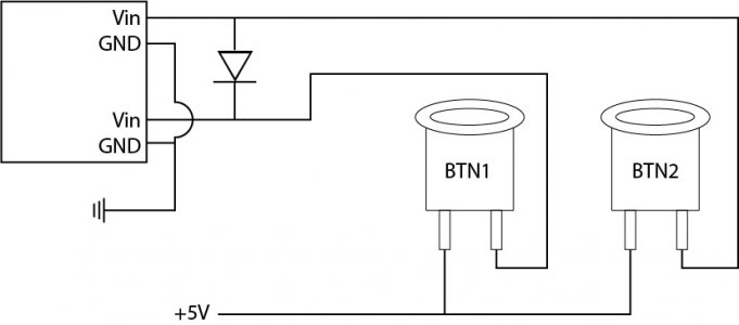
In the following schematic, I want to control both inputs with one button but only one input with the other.
What does this circuit do?

Is there a better, easier, way to accomplish this?

The diode is to keep the backflow out of the equation.
cntrl buttons.jpg
 
Let's call the Top Vin -> Vin1 and the Bottom Vin -> Vin2.

BTN1 will affect Vin2 because the diode blocks the positive signal provided by Btn1.
BTN2 will affect both Vin1 and Vin2 because the positive signal will be conducted by the diode.

If Vin1 and Vin2 do not have a resistor connected from Vin to GND internally then you will need them connected externally. Maybe something like 10 K Ohms from each Vin to GND. If not, the Vin may "float" to some unknown voltage and affect the input.
Great.
So I could flip the diode and have Btn1 Control ONE input and Btn2 control two of them.
I should have said these are momentary switches.

Why would the voltage float? I don't know if the inputs are internally resisted. They are stepper motor drivers and I'm trying to have one button run forward while the other one would run reverse. With this diagram, if I accidentally pushed both at the same time it would be the same as pushing the button that controls both inputs.
 
Yes to your first question.

First, I doubt there is a lack of internal resistor but the diagram didn't have that information. If there is no internal resistor then there is the possibility that the input will be sensitive to noise or leakage currents. Best to know for sure before your stepper moves something unexpectedly.

Yes to your second question. No harm in pushing both.

What is the stepper motor driver make/model? Could be helpful to know that.
 
One other thing that I just thought of. It will depend on the details of the stepper driver. There is something called switch bounce that could be troublesome. When you push the button, the button does not instantly go from off to on and vice versa. There is switch bounce that can happen for a few milli-seconds. This could move your stepper more than one increment because the stepper driver might see: ON-OFF-ON-OFF-OFF-ON-ON-OFF-ON, and move 4 increments in this simple example. It really depends on the details of the stepper driver.

Typically, if not built into the stepper driver circuitry you might need to "debounce" the switch input by using a resistor-capacitor circuit.

What are you building?
 
Yes to your first question.

First, I doubt there is a lack of internal resistor but the diagram didn't have that information. If there is no internal resistor then there is the possibility that the input will be sensitive to noise or leakage currents. Best to know for sure before your stepper moves something unexpectedly.

Yes to your second question. No harm in pushing both.

What is the stepper motor driver make/model? Could be helpful to know that.
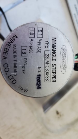
Proof of concept motor will be an obscure NEMA 23 that was RFE. I have a half dozen of them so I'm not worried about killing them.

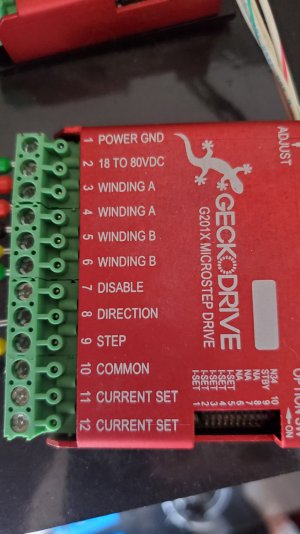
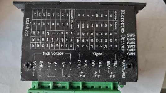
The drivers are pictured below.

The black driver had some problems with feedback from the prototype motors so I bought the red ones. The red ones didn't have that problem.
I know there's a term for it but I don't remember right this second.

Final motor would probably be a motor from Steppers online. I'm on the fence between this one
And this one
The second one has less power so it might be stalling before damaging anything if it was going to deep. It also has a smaller form factor (length) so less likely to be in the way of anything else, though not by much.

20230621_104801.jpg
20230621_104847.jpg
20230621_104904.jpg
 
One other thing that I just thought of. It will depend on the details of the stepper driver. There is something called switch bounce that could be troublesome. When you push the button, the button does not instantly go from off to on and vice versa. There is switch bounce that can happen for a few milli-seconds. This could move your stepper more than one increment because the stepper driver might see: ON-OFF-ON-OFF-OFF-ON-ON-OFF-ON, and move 4 increments in this simple example. It really depends on the details of the stepper driver.

Typically, if not built into the stepper driver circuitry you might need to "debounce" the switch input by using a resistor-capacitor circuit.

What are you building?
I'm not worried about bounce. I won't use the buttons for anything precise. I'm adding a pulsing dial for that. I may have to add a debounce to that though. I may even run that through an arduino.
I'm mainly using the buttons instead of a handwheel for repeated movements.

Building? The buttons will sit where the Y-axis handwheel is on the lathe/mill machine. I am preserving the handwheel function also. It's just to save me from getting carpal tunnel.

I will have two buttons on one side of the handwheel that are front to back and control the Y. On the other side of the handwheel I will have a side by side buttons to move the X.
 
Gecko does have inputs that are safe without pull-downs. Likely the microstep driver too. They generally have optical isolators to help with noise issues from the wiring.

Probably in the manuals you will find how long the "direction" input must be stable before providing a "step" signal. Since you are using a mechanical switch, this could be unpredictable if you push both at the same time. You will want a debounce circuit I think. It might be possible to put a bigger capacitor on the "step" signal to slow it down relative to the "direction" signal.

How about one of these to make things simpler? I have never used one but it might cure many ills.
Amazon: "Stepper Motor Driver and Controller, Forward and Reverse Control Drive Angle Pulse Speed PLC Serial Communication, DC 5~30V/4A Universal for NEMA 17/23 Motor"

[EDIT]
(Just read your last text. This might not work for that application very well although it would be good for getting a feel for the stepper.)
For the step/direction inputs, each time you push the step button moves the stepper ONE step. To make a full rotation for the stepper you picture would take 200 button presses unless you are "microstepping", which could require many more button presses per rotation.
 
Last edited:
Forgive me for asking, but are you sending command pulses to the driver, or trying to control it with switched power only?
 
How about one of these to make things simpler? I have never used one but it might cure many ills.
Amazon: "Stepper Motor Driver and Controller, Forward and Reverse Control Drive Angle Pulse Speed PLC Serial Communication, DC 5~30V/4A Universal for NEMA 17/23 Motor"

[EDIT]
(Just read your last text. This might not work for that application very well although it would be good for getting a feel for the stepper.)
For the step/direction inputs, each time you push the step button moves the stepper ONE step. To make a full rotation for the stepper you picture would take 200 button presses unless you are "microstepping", which could require many more button presses per rotation.
Yes, that drive controller is way above my pay grade.

As for the button presses, I forgot to mention I have a pulse generator that will be providing input to the buttons. It has a nice square wave and has an easily changed frequency. It's cheap and probably temporary for prototype purposes but it's a mainstream device.
 
Back
Top