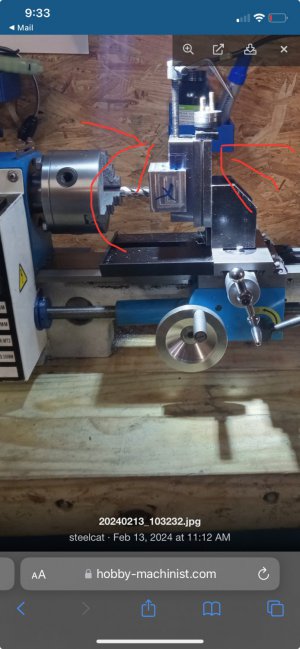
Yeah you would have to shim it. When used as a lathe this angle wouldn’t matter. It’s possible it’s all the way at the carriage level. It’s not really something they would need to dial in. It would change the height of the lathe tool if you rotated the compound but most people aren’t running the tool facing the tailstock(outside of setting its height which would be the wrong height if the compound is at an angle)
Edit:
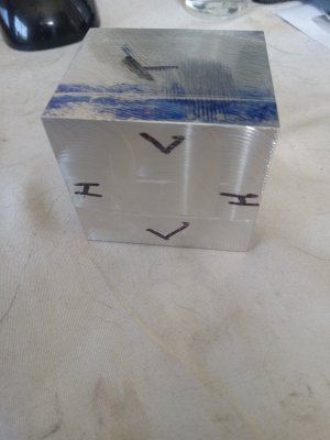
After thinking about it, your block is cantilevered over the side, it could be the weight of everything. You could also run it how it is if you could always orientate it in a way that you could run it horizontal and then sand the ridges down after.