Tell me about this 14-1/2 x 6’

Mine is the tool room version, so it at least came originally with a collet system, including the rack but I’m not sure about the collets.

I don’t know what kind of tooling Uncle had hidden in the cabinet, but I will be investigating that tomorrow.

Rick “not hitting any buy buttons yet” Denney
 
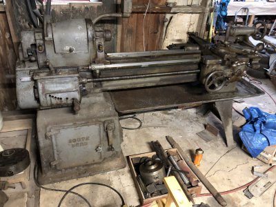
Made it back over there today and consummated the deal. I am now the owner of a South Bend 14-1/2” lathe.

IMG_9254-dsqz.JPG


Much more investigation today.

1. The serial number is 168940, which I think dates it to 1946. Definitely pre-‘47 because of the old-style number.

IMG_9250-dsqz.JPG


2. It uses the 2-1/4”-6tpi threaded spindle nose speced for that period. It also has the single-tumbler QCGB that they used at that time.

IMG_9270-dsqz.JPG


IMG_9273-dsqz.JPG


3. The 3-jaw chuck is a 7.5” Rohm. It works smoothly and just needs to be cleaned up. I found two additional sets of jaws.

IMG_9271-dsqz.JPG


4. The 4-jaw chuck didn’t have a label I could find, but despite the surface dust is well lubed internally and all four jaws move smoothly. The same chuck key works for both chucks.

IMG_9272-dsqz.JPG


5. The collet system is mounted on a threaded adapter that screws onto the spindle nose, and uses a two-stage set of collets. I’m a beginner on the topic of collet systems (except for ER collets and the 8mm watchmaker lathe collets I use on my Peerless). This one is unfamiliar to me, but that’s probably just my ignorance. What can you tell me about it? All the collets are oily, with a couple of exceptions. I did not see any 4c or 5c-type collets or a drawbar. I also didn’t see the spanner for this holder, but it’s probably there somewhere.

IMG_9266-dsqz.JPG


IMG_9261-dsqz.JPG


6. Oil was standing in the cups. It does not appear that this lathe was ever run dry.

IMG_9275-dsqz.JPG


7. I found a 7-1/2” face plate threaded for the spindle nose. I would have preferred to find a larger one, but I don’t know why.

IMG_9269-dsqz.JPG


8. The motor is a Dayton 5K482, 2-HP, wired for 110v. I think he just plugged it into the wall, and it has a standard NEMA 15-amp plug on the cord. The motor pulls 25 amps, though, so I’ll probably install a 30-amp, 120 VAC RV circuit for this late. I already have the breakers for it, and a fresh spool of 10-Ga. Romex. I may also rewire it for 240 VAC.

IMG_9259-dsqz.JPG


9. There are lots of goodies—boring bars, lots of HSS cutting tools, a couple of tool holders, scraps, tapered stock, dead centers, etc. on Monday I’ll dig further and catalog what’s there.

IMG_9253-dsqz.JPG


IMG_9267-dsqz.JPG


IMG_9268-dsqz.JPG


I have a set of low-profile machine skates on the way that can be pinned to the anchor-bolt holes—that’s just the first step in planning the move. Much more to be done there.

Rick “back on Monday for cleaning” Denney
 
The spindle should be 2-3/8 x6, a size shared with the 16 inch lathes.13's and heavy 10's are 2 1/4 x8. I don't recognize the collet system. South Bend used 3C and then 5C. Both the spindle sizes above used 5C.
 
The spindle should be 2-3/8 x6, a size shared with the 16 inch lathes.13's and heavy 10's are 2 1/4 x8. I don't recognize the collet system. South Bend used 3C and then 5C. Both the spindle sizes above used 5C.
In the late 40’s, SB converted the spindle in the 14-1/2 to a larger size, going from a maximum collet size of 3/4” using 4C collets to a maximum size of 1” using 5C collets. Both were available for a time, apparently.

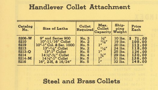
Here are some excerpts from the accessories catalog of 1950, when both were available. First shows the collet drawbars:

AFB87EAC-41D1-47EA-A5CA-8710F18F1201.jpeg

Notice the two listings for 14-1/2” lathes—for No. 4 collets and No. 5 collets, respectively.

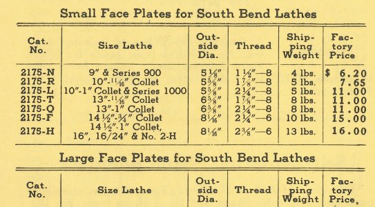
And here is the listing for the accessory faceplates, showing the different threads.

F5D77FF7-D1BF-4BB4-B2BB-21D863915895.jpeg

The smaller spindle uses a 2-1/4” x 6tpi thread, and the larger is the 2-3/8” x 6tpi thread as used in the 16.

The 13’s also came in two sizes.

In any case, mine is a 2-1/4” spindle. Here’s the back of the collet chuck:

17254230-2F2E-45D9-8B49-8CF23BED4FDE.jpeg
(I left it big so you can zoom in on it.)

I would have preferred the much more common 2-3/8-6, or even the 2-1/4-8, but it is what it is. There are a few of the collets in the pile of stuff, but I don’t know what sizes, nor do I know how much they’ll shrink and stay true. I’ll have to pull the 3-jaw and mount this to see what I’m dealing with. I don’t know what shape is inside the spindle as of yet. I’ll take some measuring equipment Monday.

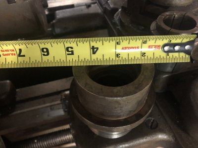
Edit: The inner sleeve of the collet is 1-1/2” in diameter, and the opening in the clamp ring is 2”. I see a collet that is over an inch inside—exploring the full width of the through bore. But I don’t see more than 8 collets, and all of them are bigger than a half—maybe 5/8 to 1-1/16 in 16ths—but that’s a guess.

Rick “unable to find even a hint of what type of collet system these are” Denney
 
Last edited:
Since it is a tool room version, it originally shipped with a collet system. The handwheel version was standard, but could be upgraded at time of purchase to a hand lever version. The system you have is unfamiliar to me. No collets were included in the purchase price. Depending on the spindle bore, it probably used a 5C collet system. Search around for a collet closer tube and spindle collet closer. The stock system would be superior to what you have now.
 
Since it is a tool room version, it originally shipped with a collet system. The handwheel version was standard, but could be upgraded at time of purchase to a hand lever version. The system you have is unfamiliar to me. No collets were included in the purchase price. Depending on the spindle bore, it probably used a 5C collet system. Search around for a collet closer tube and spindle collet closer. The stock system would be superior to what you have now.
Agreed, though this spindle used 4C collets. I think I see what has happened. The advantage to what is included is that it provides a range up to the full through bore of the spindle, which is 1-1/8”. The 4C collets max out at 3/4”, so the collet chuck I found would supplement the original range. Yes, I will be looking for the collet closer and drawbar—4C collets are expensive but at least they are available.

The chuck I have looks more like a tool-holding system, but that is likely what I would use it for anyway. I don’t own a mill, and I’ll need to do a bit of milling on the lathe.

Rick “suspecting the drawbar and closer is in the pile somewhere” Denney
 
Okay, here’s the latest.

How many of you noticed the apron gear change handle was not there? Yeah, me neither. :( I found the handle, and it appears to have cracked across the shaft of the idler gear shifter. Of course, that part seems to be unobtainium for the 14-1/2–old parts list show it as “NLA” and don’t even provide a part number.

At least it’s in neutral.

So, what to do? I could machine using the lead screw at 224 tpi—about .005 per revolution. But of course I have also lost access to the powered cross-slide. I’ll need to figure out 1.) what caused it to break, and 2.) what repair is possible. Is it cast iron? The fracture surface suggests it. Maybe I could drill down the shaft, install a Grade 8 bolt, and then braze around the outside. I’m not sure I’d trust brazing by itself. I have a buddy who I do trust with brazing and welding.
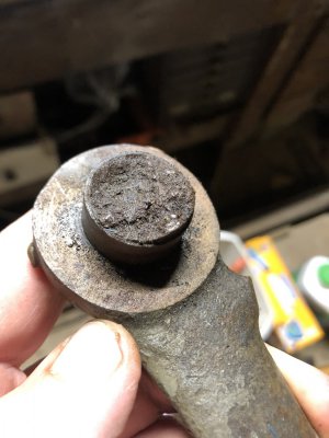
image.jpg

The belt must be replaced. It sorta works but it’s not tight enough to drive higher speeds. But I was able to test the QCGB, the back gears, the reverser, and the speed selector in the gearbox under power.

The weird collet chuck has collets for 5/8, 3/4, 7/8, 1, 1-1/16 (two of them), 1-1/8, 1-1/4, and it will hold 1-1/2 without the inner part. I found the spanner, and it is definitely shop-made.

The micrometer stop is frozen up—I doubt it was ever used. I can fix that. And the saddle clamp seems to be missing—I can fix that, too.

The spindle is definitely the old style 1-1/8” through bore with 2-1/4-6 nose threads intended for 4c collets. The good news is I have sourced what appears to be the correct drawbar and closer, and I found the thread protector in the pile. All the chucks and plates install happily, though the 4-jaw is a heavy thing.

I found a shop-made fixture plate plus the factory face plate, both of which are 7” in diameter. I may use the shop-made as a mule to carry a 12” plate.

I also found a range of scraps and cutoffs, so I’ll be able to play without sourcing new stock.

Finally, I learned that Uncle bought it from a guy who used it to repair airplane propeller hubs. Both of them were colleagues teaching airplane mechanics at the local trade school. I’ve inspected the ways again and they appear to be unworn.

I’ve reserved a tilt-bed trailer for the move—targeting Thanksgiving weekend.
EF04F440-FBC0-40D4-82E6-62D4EEA3D70B.jpeg

Rick “runs fine on 120VAC, but with no load” Denney
 
Which handle is broken?

Maybe I'm missing something... the only handle I don't see is the backgear engagement... it looks like all the apron controls are there...?

-Bear
 
I agree with Bear... I can't see what handle is broken. The apron selection shifter is still there (at least in the photos).

SLK "color me confused" 001.
 
In post 32 there is a hole where the shaft goes, then just above the arm is in place.

Did you stick it in for fit?

It moves a couple thinks and one is an interlock that only allows 1/2 nuts or feed.

So something may have been in wrong place when someone who eats bananas and walks on their knuckles used it.

I would not weld or braze yet.

Tear the apron off and inspect everything and see that it all moves.

Fracture breaks like splintered wood are gifts...

They have a unique pattern that will only align one way.

We had the support for the reversing shifter for the threading gears do same on our 1917 model A.

Did the below with just the bolt and epoxy.
So, carefully alignment and clamping will get the handle in correct position.

Once you confirm that you can fit the pieces together you now can repair.

First, properly clamp the inside piece so you can drill a 1/8 hole in the center of the shaft inline with the shaft.

Remove burrs from broken end and make sure both parts still fit.

Now clamp both parts together and using the drilled hole as a drill guide bushing, drill the hole into the handle part.

Go all the way through, bonds can fill it in later.

Depending on the shaft size, determine the bolt size.

Maybe 1/2 inch, I like fine thread but coarse may be better in cast, others may have better answer there.

Drill final tap size while clamped tight.

Now tap just one part.

Remove any burs and clamp bacteria together then tap the rest of the way through.

Now thread a bolt through to see how they feel.

There may be some slop.

Things to think about...

If you drill out one side then the bolt can draw parts together but now the bolt head.

You can use just a good grade bolt with long enough threads to thread all the way through, this is full engagement on both sides.

Leave the head on until finished, then cut the bolt at the points it leaves the part and putty and sand to prepare for paint.

1.
Scrub clean with acetone and mix some good slow cure epoxy, we use Devcon HVAC, expensive but made to repair leaky condenser and evaporator so strong stuff.

Slow cure allows you to slather it in both threaded holes, the faces and the bolt then let it cure a few days before cleaning up.

2.
One can solder with lead solder and GOOD FLUX to insure solder flows all the way, you add to top until it comes out the bottom.

3.
Or, you can silver solder, requires more heat.

4.
Or, you can do as South Bend does, get some 1/8 ROUND like drill rod and carefully drill a 1/8 hole parallel to the bolt but center of hole at the line where the bolt and part meets, this is common on some SB knobs.

I would NOT attempt to braze it before the bolt as you have one chance and it will be ugly and not near as strong.

Sent from my SM-G781V using Tapatalk
 
Back
Top