Small face mill using tangential cutter

Brino:
Please note this concept is what Homebrewed came up with at the beginning of this thread.
I am just expanding upon his idea. To take it from a simple small Face Mill into a larger Flywheel base Fly Cutter suitable for the low torque Mini Mill. At the speeds for a Fly Cutter to operate and provide an optimal finish the Fly Wheel inertial forces should minimize the actual low torque or the motor. The simplicity of the Fly Cutter with the added cutting ability of the Tangential cutter and simplicity of the single facet grind to the tool bit should provide for an enjoyable build and hours of pleasure watching the magic of a simple home made tool provide a masterful cut and finish.
 
"I will mention that Gary of Eccentric Engineering says that a V on each side creates a stronger clamp than using a Square trough on each side. This is how the Diamond tool holder is designed to clamp onto the tool bit in either round or square stock."

In that case two 90 degree Vees make a square rotated 90 degrees, but it's capable of accommodating round and square bits. That's not a bad suggestion....but....as Brino mentioned, you don't want the split to line up with the fixing screw (or fixing force). So in this case the screw must be on the radius and act as a set screw, not part of a slit/clamp scheme.

As far as making the round holder with the internal Vee. There are 90 degree end mills. Or a standard flat end mill could do it if the work is tilted 45 degrees relative to the EM but the challenge is getting the dimensions right -- the depth of the groove affects centering as well as the width of the vee.

I'm wondering if you could mill a vee in two pieces of square stock, fix them together and then turn them into a cylinder. There would be a lot of steps that could go wrong there, but no more than what you'd encounter if you start with round stock and try to go the other way.
 
The case of using the Round milled with the split square centre the clamp action is provided by the split on the Flywheel clamping down on the split cylinder held in the angled hole of the Flywheel. OR this is is my envisioned concept as of this minute.
All of this presents some challenges in the milling and Turning.
If you have or have seen the Diamond Tool holder you will note in the relaxed state the clamping jaws do not quite meet and in the clamped state there is quite a separation between the two parts of the clamp. So I do not believe the concentric behaviour of the clamp will be a huge concern and the actual clamp is the Flywheel clamp acting upon the split clamp of the round plug with the squared hole in the middle. I hope I am describing my idea correctly.
The Round inner clamp is being squeezed by the Larger, Split in the Flywheel squeezing down upon the round clamp.
They is where I wish I had the tools and the ability to draw the concept as an image. then I would be, much more clear as to the approach I am attempting to apply
 
Screen Shot 2020-12-20 at 13.02.59.png
1. I have drawn a Circle to represent the Flywheel
2. next I drew a second smaller circle to represent the drilled hole
3. I attempted to draw a square within the smaller circle
4. I attempted to draw a line through the square which bisects both the inner circle and the square.
5. I drew another line on the flywheel cutting through the flywheel beginning on the leading edge of the smaller circle and continue to the edge of the flywheel
6. I drew a line to represent a single screw on the trail edge of the inner circle which is to act as the single clamping screw clamping the flywheel onto the inner circle clamp which holds the square or round tool stock in the split circle clamp.
Does this poor drawing help anyone to better understand what I am proposing.
Comments please
 
I could hand draw this picture and add Labels to the portions to better define my idea.
I know how to draft but it has been over 40 years since I last did any serious work.
 
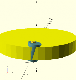
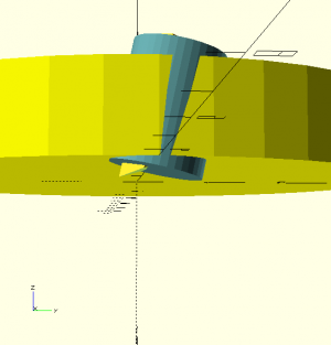
@courierdog, using OpenSCAD I created a very pared-down version of what you're proposing. Some renderings are shown below.

There are some obvious things that need to be addressed. First, the diameter of your round tool holder is too large, or the diameter of the flywheel needs to be increased.

Second, the toolholder needs to be pulled up a bit so its heel doesn't rub against the work. This is less than ideal because it means more of the cutter is unsupported. Milling the bottom of the holder so it is flat relative to the body would improve this; but see the next paragraph.

Third, it's my understanding that for best performance the cutter needs to intersect the work so its cutting action is parallel to the swept-out circle being machined. This won't happen unless the holder is offset, because the cutter is coming out at a 12 degree angle. You need to define how much cutter stick-out you want. Yes, you could rotate the holder but it could be difficult to rotate it just the right amount; and if you mill the bottom of the holder to flatten it, you want to KNOW what the correct rotation angle is. Better to set things up so it's easy to install the cutter correctly.

These renderings were done with a body diameter of 7 inches, a toolholder diameter of 1 inch and offset to machine a 6 inch diameter circle. It was tilted 12 degrees. I also added the 30 degree grind angle on the end of the cutter.

This study required 39 lines of OpenSCAD code (including comments).

face mill study 1.pngface mill study 2.png
 
homebrewed:
You got the basic concept

Yes the interior round (Plug) clamp only has to be big enough to hold the Square or Round (nominal 1/4 tool stock)
Yes the bottom portion will have to be milled such that it is mostly flush with the base.
If we back up and look at the Diamond Tool Holder and how the tool Turns or Faces metal on the lathe.
The two extremes on the cutting angles, worst case 10 degree rotation.
Once the actual optimal cutting angles are defined for the type of cut or finish is defined very little of any rotation will be required.
I have found when using the lather I have one QCTP insert set up on the Right hand tool and the other holder set up on the Left hand tool
The amount of projection of the actual Tool is held to only what is required.
This is straight forward when dealing with the flat surface finish
Let us now consider using the same cutter to create a step cut along a side of a bar
Example we want to cut a square bar.
The design calls for a 1/8 inch deep by 1/8 inch wide.
Doing this with a Fly cutter is more time consuming but we are talking a simple home work shop where the cost of purchasing a tool may be out of the question.
We have this newly created Flywheel based fly cutter so now we are looking at cutting (slowly) a step into the side of a piece of metal.
So in this instance the cutter will have to be strong enough (reason for the 1/4 inch tool stock or even 5/16 tool stock) so the tool bit can safely extend beyond the base of the Flywheel Tool holder.
Now go back to my poor drawing,
The Flywheel needs to form the clamp of the tool held inside the split cylinder.
I think we are now on the same page.
Back to you for your comments
 
@homebrewed:
Please keep in mind, the objective is a simple amateur machinist project for construction using a mini lathe and mini mill.
The spindle is a nominal R8 which is used on the majority of Mini Mills. The current Mini Mill uses a 500 watt brushless motor.
These motors work well using higher RPM and thus the use of the Large and Heavy Flywheel which has the spinning mass to mitigate the interrupted cut of the Fly Cutter.
The vast majority of Fly Cutters have little mass and a very unbalanced and potentially more dangerous rotating cutter which cannot be seen and leaves the all too real risk of something being snagged by the spinning mass. I have seen this happen and it a very messy sight when a person looses his/her mechanical safety concentration.
My ideal spinning mass should be totally without projections which can snag any wayward appendage or loose material.
The cutting side of the tool is the only place where cutting action should happen.
The design goal is for the visible, upper and the periphery surfaces should be virtually idiot proof.
I hope this makes sense and allows you to better see my minds view.
My mill is a MicroMark benchtop mill with a 500W brushless motor as well. R8 spindle. So I'm dealing with similar machine limitations.

Milling a step with this proposed tool will be limited by the stickout of the cutter. Clearly there is a limit to how far out it can project before you run into problems, so there will be a limit to how high the step can be. The rectangular cutter definitely is the one you want for this, a round cutter will produce a rounded corner on the bottom.
 
@homebrewed:
Just to clarify, My Mill and Lathe are from the Little Machine Shop. The Mill is the 3960 and the Lathe is the 3536 8.5 x 16
My thoughts on the initial maximum DOC is a nominal 1/4 inch absolute maximum is 1/2 inch but this has to be worked on to design this for the Amateur Machinist who may will push things beyond the specified maximum.
Designing a tool which can be built simply which can be employed to make and do things without the need to buy expensive insert based tools and more importantly sharpened by the Amateur Machinist.
A single facet tangential cutter is able to cut much more that the average multi-facet tool which requires more time and practice to accomplish and does not last as long when actually cutting metal.
 
Back
Top