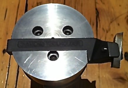
Small face mill using tangential cutter

Some progress, on the proposed Flywheel Fly Cutter, thanks to input from several people.

1. Mass and Diameter nominal 6 inch cutting radius
2. Tool Holder, Square Collet style tool holder, the Collet allows the tool to be rotated within the Flywheel for the optimal cutting angle. the collet approach is what I was thinking all along but did not have the terminology to define. Now the idea have been suggested that the tool may be pushed back by the forces of the Interrupted cut. Hence the concept of the collet to hold the Tool bit.
a straight shank is simpler but a slight taper would possibly provide a more secure clamp and resist tool push back.
3. Flywheel drilled such that the Nominal Tangential Cutting angles are a result of the angle and direction of the hole drilled in the Flywheel. the collet is proposed to be clamped into the mass of the Flywheel. Please note the 12 x 12 angle is up from the horizontal not down from the vertical. I hope that makes sense. al describes this in his approach Tangential Fly-Cutter https://www.cgtk.co.uk/metalwork/sx3mill/tangentialflycutter
4. Spindle attachment to Flywheel, proposal is an R8 FMB22 Arbor, this allows the arbor to be removed from the Flywheel for storage between uses.
Now can some other voice be heard on this and I know we have people who can apply a CAD drawing to this modified concept.
It is really great working with so many wonderful people who have brought so many ideas to this concept. I certainly do not take credit for the design. my only contribution is a feeble attempt to bring the idea together where it can be built by even the novices on the forum. This last part is where the vast wisdom of the collected forum can be utilized to bring the design and machining techniques to focus on a project which enable the novices to build a usable tool with simple, tooling and the written guidance of senior members.
Stay Safe, Stay Sharp, find a fresh sheet of paper and put your thoughts on paper then, fingers to the keys for input to this collective project.
Happy New Year
 
Since the cutter in your latest approach is inclined just 12 degrees from horizontal, that will substantially affect your collet design. It may need a conical nose in order to keep it from hitting the work before the cutter does.

If you haven't done it already, I'd suggest getting out your mechanical drawing stuff and start drawing in order to see what constraints you're dealing with. Scaling the dimensions up will make it easier to draw, and won't alter the geometry.
 

homebrewed:​

My collet for lack of a better term is a round external shape with a square inner shape.
IT has been been suggested I also require a physical adjustment to prevent push back of the tool bit into the Fly Cutter Housing this will complicate the current approach.
As a Starting point this would mean a blind hole with the opening at the point where the tool bit is facing the work piece. The Rear or the blind hole bottom will facing away from the Work Piece. If required it will be threaded to allow for a threaded screw and lock nut to secure the working position of the tool cutter. The hole drilled for the collet will be be clamped using a split cut through the flywheel bisecting lengthwise the collet hole. The actual clamp at this point will be a single screw located toward the tool bit exit and above the tool bit.
Any suggestions at this point.
The DIY tangential toolholders for lathes that I have seen don't have a screw underneath the cutter to prevent push back. Maybe it's a solution looking for a problem?
 
I was thinking more along the line of the clamping screws on the periphery and the potential stop and adjust met screw would also be from the periphery.
With everything that the current concept the thickness of the Flywheel is increasing.
1. the original cutting diameter is a nominal 6 inches or a nominal 6.6 inch diameter plate
2. the original thickness of the of the Flywheel Plate was 1 inch mow this has grown to a nominal 1.5 inches
3. I am still looking at the collet style toolholder with the hole drilled into the Flywheel at the nominal Tangential 12 x 12 degrees so the actual tool bit can be sharpened as a typical Tangential Lathe tool bit.
The only reason for the circular Collet style tool holder at this point is to allow for some degree of rotation of the tool bit to achieve the optimal cutting angle. With the Tangential Tool it is extremely important to optimize the tool face to the work piece for optimal cutting and finish plus the ideal is to transfer as much heat into the removed chip and away from the tool and the work piece. This is a delicate balance of the angle of approach and the tool grind applied to the cutting bit.
The idea of the collet is to optimize a clamp for a square tool bit that can be rotated to achieve an optimal cutting angle.
I was thinking of four pieces surround the tool bit and turn in the lathe to size to the point of minimal external collet while providing a means to hold in a split clamp with in the Flywheel.
More thought is required on how to accomplish all of this using the KISS principle.
Thanks for Listening
 
Flycutters freak me out a bit as they whirl around looking unbalanced and ready to fly apart.


Sent from my iPhone using Tapatalk
When I first started working in a machine shop I knew nothing about the trade. A co-worker had a milling machine all set up for me to do some fly cutting. All tooling was made in house and the fly cutter used a couple Allen head bolts to hold the cutting bit in place. This co-worker said "Make sure that bit is tight.......I'd hate to see you wearing it in your chest." As it turned out fly cutters were one of my favorite things to use.
 
I can agree with you watching a Flycutter in action is like watching a plotter draw a circuit board. Watching a Face Mill or an End Mill does not have the same appeal of a Fly Cutter up against a huge piece of uneven metal.
This is especially true where the Fly cutter has a large diameter and the work piece starts as a very uneven rusty hunk of cast iron.
The speed is slow and the cuts are extremely fine to prevent mishap with no lubricating fluid used. while hard on the work piece, the cutter bit and depending on the care used on the machine and tool setup can tarsier a lot of the shock of the interrupted cut to the Spindle.
Using a Large Flywheel and care is given ensure as much balance as possible is given to the cutter set up, the mass of the flywheel resists the sudden slow down effect of the interrupted cut. This is where the Tangential cutter comes in. The concept of the Tangential Cutter be it on the Lathe or the Mill is such that the cutting angle is much more efficient and transfers more of the heat to the removed chip, less to the cutting tip and thus the Cutting bit and the work piece remains cool.
There are those who live the Tangential cutter and those that hate the Tangential cutter.
If you look at the current high end milling tools you will notice there is a move to Tangential Insert cutter for the Mill claiming tremendous increase in the speed and efficiency of the removed metal.
I find this move by the commercial concerns very encouraging as it does point the way forward.
While those of us in our tiny home shops are not going to rush out an purchase an expensive cutting tool we can move forward in small ways in adapting the concepts in a small single facet cutters such as the Fly Cutter to achieve in a small and slower means the principals employed by the big machine shops and do it on a very lean budget.
 
Home-brewed
I received an email from Gary Sneesby of Eccentric engineering, he sent along a photo of his version of a fly cutter.
This uses the Diamond Tool Holder as the tool bit holder.
In my case this will require a nominal 4.5 inch diameter concentric disk made to attach to an R8 Arbor such as an FMB22.
On the one side it will require milling to allow for fitting of the R8 Arbor
on the visible (as Shown) a nominal 1/2 slot x 1/2 inch deep with a notch cut to allow the Diamond Tool Holder to have some of the clamp mass inside the circular disk mass.
On the edge would be three to 4 clamping screws
Under the shank of the Diamond Tool Holder would be an R8 Arbor holding screw.
While it may look a little awkward I think as I work through the various dimensions, drillings and milling cuts it should be a workable solution.
IF anyone has a suggestion I would appreciate it.
I like using the Diamond Tool Holder, and if I am able to make a means to secure it to the mill in a safe manner and allowing the tool to be used as a Flycutter.
 

Attachments

  • photo 1.jpg
    photo 1.jpg
    41.1 KB · Views: 15
I've also used the diamond tool holder as a fly cutter.
page 6 and 7
I can see a purpose built holder is way better.
 
Savarin, it is good to know, others have tried using the DTH as a Flycutter.
Note: After reading your apology at the bottom, your first statement made a lot of sense.
I was afraid people would think I was a little of the level for even suggesting it.
My rational is to try Garry's suggest as a proof of concept, of the Tangental Cutting process configured as a FlyCutter.
After the Proof of concept is built and providing it does work as intended,
Decisions can only be made after proving Garry's concept.
I am working through the design in my head, trying to think through how to draw it, so it makes sense.
There are three levels
Top - Arbor Fitting
Middle Attachment Plate
Bottom Diamond Tool Holder Clamp.
Have I missed any thing.
 
Back
Top