-
Welcome back Guest! Did you know you can mentor other members here at H-M? If not, please check out our Relaunch of Hobby Machinist Mentoring Program!
You are using an out of date browser. It may not display this or other websites correctly.
You should upgrade or use an alternative browser.
You should upgrade or use an alternative browser.
Small face mill using tangential cutter
- Thread starter homebrewed
- Start date
- Joined
- Nov 4, 2012
- Messages
- 52
While a purpose built tool is always, better, as it should factor in more of the cutting details.
I want to start with Gary's concept, to get a better handle on the fly cutting concept while using a tangential cutting face.
While the diameter of the resulting tool is technically outside the operating parameters of the Seig X2 Mill it should be capable from a proof of concept stand point.
Creating a stand alone tool involves an entirely different approach. While adapting Garry's concept while quire physically large should be manageable. IF, I can work out at the dimensions and cutting solutions.
It would be nice if I had a local machinist friend to sit down and discuss how to approach the project.
- Joined
- Nov 4, 2012
- Messages
- 52
savarin:
Until I looked up Townsville on the Map, I had no idea you lived way up in Queensland, that is 28 hr 16 minutes or 2635 Km to Melbourne which is comparable to Edmonton to Toronto 34 Hr 2 Min or 3335 KmWe both live in rather large countries.
My daughter moved to London UK as she can travel (prior to Brexit and COVID) to Europe easier and cheaper than from Canada.
I have driven from coast to coast, Halifax to Vancouver and gone over to the Island to Victoria via the ferry.
As a drive that is 58 hours 12 minutes or 5781 Km Not a drive for the winter time as the snow can be terrible and the ice is treacherous.
Here the high of the Simmer is +35C while the low of the winter is a nominal -40C
My sister moved back to Nova Scotia when she retired. Summer +19C Winter -9C
- Joined
- Nov 4, 2012
- Messages
- 52
It has been a few days now. I was hoping for more comments and other input. Homebrewed came up with a simple solution. However, I would like the tool bit to laid down so to speak. 12 degrees from the Horizontal rather than 12 degrees from the Vertical.
1. Have the tool bit rotated 12 degrees outwards from the tangent point and at right angles from the centre.
2. Have the tool bit tilt downwards from the horizontal by 12 degrees.
I have been attempting to draw this on paper and am having some difficulty. While I know what I want in my head, putting it down on paper is not easy. I also attempted to use the various drawing applications I have any I am unable to get my head around the applications to make anything useful.
If only I could sit with or explain to someone who has the time, patience and ability to take an idea and bring it to life, so to speak on paper (Computer screen)
Well it is a thought, which requires a person with a different talent which I do not possess.
Thanks for Listening
- Joined
- Jul 28, 2017
- Messages
- 2,384
Maybe part of the reason for the absence of responses is that you're looking at some tricky-to-calculate compound angles. The first one is setting up to drill the hole for the toolbit/holder, and the second is setting up to drill/tap a hole for the set screw.
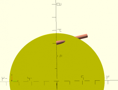
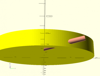
I did some fooling around with OpenSCAD and got something that may have the geometry you want, but it was done completely by using trial-and-error. And it doesn't hand you any way(s) to set up them-there compound angles.
Anyway, here are a couple of views of what I came up with, starting with a view from the bottom showing the 12-degree rotation angle around Z (which is into the screen).

And from the side:

I did some fooling around with OpenSCAD and got something that may have the geometry you want, but it was done completely by using trial-and-error. And it doesn't hand you any way(s) to set up them-there compound angles.
Anyway, here are a couple of views of what I came up with, starting with a view from the bottom showing the 12-degree rotation angle around Z (which is into the screen).

And from the side:

- Joined
- Jan 2, 2014
- Messages
- 8,853
Thanks @homebrewed that really helps me!
I was unclear on what @courierdog was describing.
I wanted to help, but felt lost....not understanding what he was picturing.
-brino
I was unclear on what @courierdog was describing.
I wanted to help, but felt lost....not understanding what he was picturing.
-brino
- Joined
- Jul 28, 2017
- Messages
- 2,384
I THINK that's what he is afterThanks @homebrewed that really helps me!
I was unclear on what @courierdog was describing.
I wanted to help, but felt lost....not understanding what he was picturing.
-brino
- Joined
- Nov 4, 2012
- Messages
- 52
homebrewed,
I think you have captured what I was thinking except I was thinking the tool bit should point outwards as opposed to how you have it pointing inwards.Having the drawing in front of me, illustrated as you have done, I really appreciate this. It does however really point out how much more difficult this method would be to build, especially if I want a square tool bit as opposed to the round tool bit you have chosen. This is why I I am looking at this with non Machinist eyes or abilities.
I come from an electronics background.
My reasoning for wanting to stay with the square tool bit is it would be interchangeable with my existing tool bits.
The really encouraging thing is how you have captured the essence of my concept with your drawing.
This is truly amazing that you have this ability and seem to be able to bring to life a concept described to you.
- Joined
- Nov 4, 2012
- Messages
- 52
@homebrewed,
What really got me was having this drawing in front of me, made the possible machining so straight forward.In my head I am trying to imagine this using a flywheel (Disc) as the basic tool holder.
I have some tooling which uses the R8 Arbor and especially the FMB22 tool as it has both the R8 plus the two pins for added turning stability. It works really well for the face mills I acquired.
I have a real soft spot for FyCutters due to their simplicity.
Again Thanks ever so much for taking the time to draw the illustration.
- Joined
- Nov 4, 2012
- Messages
- 52
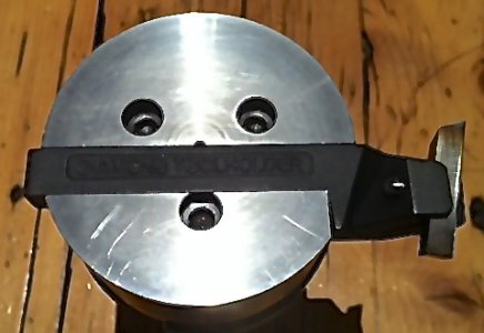
As to the reason, for the 12 degree outwards is to match the idea put forward by Gary from Eccentric Engineering.

You will notice the tool bit points outwards by 12 degrees.
After seeing your drawing I also realize this will be the road less traveled as well.
I hope this make it a little more clear as to my reasoning.
As another person already pointed out having any large unbalanced object flying about on a mill just makes me nervous.
This is what drew me to your approach in the first place.
Your simple approach is by its nature more balanced than the vast majority of the FlyCutter I have seen. Any Single Facet Cutter will by its nature be unbalanced.Thanks for your patience and your generosity in time and effort making the conceptual drawing.

