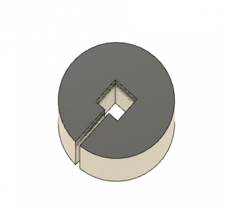
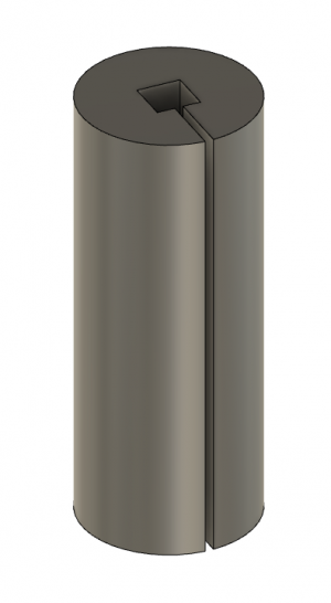
Small face mill using tangential cutter

I've used OpenSCAD to explore different cutting tool geometries. I find it handy because you create objects using a script rather than a GUI approach, so it's easy to change angles and then view the result, using its "render" operation. You can easily move the viewpoint so you can see what the cutter looks like from the workplane perspective. Here's an example of an attempt to make a simplified tangential toolholder for a lathe:
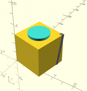
tangential simple #2.png

The standard tangential toolholder must have a slot that is cut on a compound angle, which tilts the bit forward AND sideways. I thought it might be possible to cut a single angle and then rotate the holder to get something that approximated the sideways tilt. I think it will work, but it has some disadvantages compared to a standard tangential toolholder -- most notably the possibility of the toolholder body hitting the chuck jaws, or the work hitting the body. Machining in some extra relief will probably address this, but now we're looking (again) at a more complex machining job.
 
Homebrewed:
Your Visual Tool is fantastic.
I would like, if you are agreeable to work out the angles.
In the case of the Flywheel based Fly-Cutter the cutter portion of the Wheel is so that the Tool Bit is in the centre of the cut and the direction of the split is the direction of the optimal cut line. I assume as a starting point, 1/2 inch to the centreline of the split and one allan key on either side of the tool bit to form the clamp. The amount of clamp is controlled by the amount of open split between the two pieces.
Rather than using a single screw to secure the tool bit two screw one leading and another trailing the tool bit.
I am concerned about any potential rotational angle of the tool bit to achieve the optimal Tangential Tool Bit angle.
working out to cut these cutting angles and how to achieve them.
Cutting the angle on the movable piece is a compound angle
Similar the angle on the fixed portion of the flywheel is also a compound angle
Both the movable and the fixed portion form the clamping square.
The angle must be such that the Square Tool Bit can be clamped and held at the optimal Tangential cutting angle
The Round Tool Bit can be rotated minimally to suit an optimal cut
Jut the thought of creating a more optimal Fly-Cutter that has a Flywheel to assist in the overall balance of the turning single bit cutter.
Add to this the potential of creating an Tangential cutter within the Flywheel which hoppers both a round and a square tool bit cutter which uses the simple sharpening process of the Tangential Cutter.
While the Fly Cutter is one of the oldest known machining tool cutter it fills a very valuable back stop cutter which can provide the newbie and the seasoned pro with a proven, precision cutting tool.
Thanks for Listening
 
Homebrewed:
BTW I have Qty 4 Diamond Tool Holders.
I managed to lift the LMS 3960 off the floor and onto it new workbench.
I use a system of Shackles and Pulleys and a Climbing Rope, to reduce the weight for an old man to manage by himself. ha ha
When I retired for the third and final time in July I got a Tormek Drill Bit sharpening system which allows of sharpening drill bits with a 4 Facet point. 4 Facet drill bits cut through just about any thing and retain their edge longer. Then I obtain the Acute Tool Sharpening Kit from Eccentric Engineering.
These two items alone will keep me busy for a while.
Now I have added the Flywheel Fly Cutter to the list. I will be be busy for some time.
Having time to research and shop time are very prized activities.
Thank you for being part of my inspiration.

And remember you live closer to the ocean than I do so you are more blessed, I was raised with my feet in the North Atlanic and now I am land licked in the Prairies. Poor Me
Stay Safe
Thanks for Listening
 
Homebrewed:
Your Visual Tool is fantastic.
I would like, if you are agreeable to work out the angles.
In the case of the Flywheel based Fly-Cutter the cutter portion of the Wheel is so that the Tool Bit is in the centre of the cut and the direction of the split is the direction of the optimal cut line. I assume as a starting point, 1/2 inch to the centreline of the split and one allan key on either side of the tool bit to form the clamp. The amount of clamp is controlled by the amount of open split between the two pieces.
Rather than using a single screw to secure the tool bit two screw one leading and another trailing the tool bit.
I am concerned about any potential rotational angle of the tool bit to achieve the optimal Tangential Tool Bit angle.
working out to cut these cutting angles and how to achieve them.
Cutting the angle on the movable piece is a compound angle
Similar the angle on the fixed portion of the flywheel is also a compound angle
Both the movable and the fixed portion form the clamping square.
The angle must be such that the Square Tool Bit can be clamped and held at the optimal Tangential cutting angle
The Round Tool Bit can be rotated minimally to suit an optimal cut
Jut the thought of creating a more optimal Fly-Cutter that has a Flywheel to assist in the overall balance of the turning single bit cutter.
Add to this the potential of creating an Tangential cutter within the Flywheel which hoppers both a round and a square tool bit cutter which uses the simple sharpening process of the Tangential Cutter.
While the Fly Cutter is one of the oldest known machining tool cutter it fills a very valuable back stop cutter which can provide the newbie and the seasoned pro with a proven, precision cutting tool.
Thanks for Listening

I have attached the OpenSCAD script I used in my simplified tangential toolholder study for your perusal. OpenSCAD is available for Windows and Linux (but not Macs) and is free. Of course, my particular script is nowhere near what you want but it does provide sort of a tutorial on how you might proceed. If nothing else, you could use it in a virtual cut-and-try manner to get the compound angles right. OpenSCAD has a good online user reference and there are a number of tutorials you can go through.

BTW, I had to rename the file in order to attach it. If you want to load it into OpenSCAD, change the file extender to "scad".
 

Attachments

  • tangential simple.txt
    1.3 KB · Views: 4
So now you know who owns a Mac household.
We have been Apple Exclusive since My Daughter built her first Apple II Clone, which worked BTW.
I bought our first Mac in 1983 and we currently have 5 working Mac in the house and at lease 4 more in states of disrepair.
 
So now you know who owns a Mac household.
We have been Apple Exclusive since My Daughter built her first Apple II Clone, which worked BTW.
I bought our first Mac in 1983 and we currently have 5 working Mac in the house and at lease 4 more in states of disrepair.
Oops! Sorry about that. There might be somebody out there who has come up with a Mac-specific hardware layer for OpenSCAD. I was going by what the official downloads page has.

Another possibility, although perhaps anathema to a Mac owner, is to use a windows emulator, like WINE is to Linux, and run OpenSCAD with that.
 
Homebrewed:
First My idea is a 6 inch Diameter cutting radius.
First my Flywheel based Fly Cutter is a nominal 7 inch in diameter
Second the Fly wheel is a nominal 1 inch thick.
Third the tool holder is 12 degrees round hole drilled facing the direction of the cut.
Fourth a round plug of a nominal 1 in in diameter is a split assembly with a nominal 1/4 inch square hole in the middle of the split assembly
Fifth the plug has a gap between halves to allow for proper clamping of the Square or Round 1/4 inch tool stock
Sixth the Flywheel has the nominal 1 inch diameter hole drilled at a nominal 12 degrees facing the direction of cut, the fly wheel has to have a cutter the entire diameter trailing the hole and a nominal 1/2 to 3/4 inch on the leading edge of the hole. The split in the Flywheel will allow a single clamping screw to clamp the round plug with the square hole in the centre.
Seven the purpose of the round plug is so the Square tool bit can be rotated to facilitate the optimal cutting angle regardless of round or square tool stock used.

I do not have the ability to draw what is in my head so I hope my words describe it sufficiently for you to grasp the idea.
While I am unsure how to make some of the milling cuts to form the Square clamp with in the Split Round Plug I am sure with your expertise this would not be a problem.

Such are the wild machinations of a retired old man with time on his hands.

The difficulty as I see it is the milling of the two half squares in the split halves of the round stock turned to fit the 12 degree hole in the Flywheel.

If this concept can be made to work it should be possible for people to build.

What I am learning about the mini0mills is at the low revolutions a Fly Cutter requires is where the brushless motor has the lease amount of torque. The use of the Flywheel will enable the amateur machinist to more effectively use a Fly Cutter to achieve results with a home made tool

I hope this makes sense to you.
 
Like this?
(although I think you meant fully split into two parts)

1608435364109.png

1608435369213.png

I modeled it in Fusion-360. OD=1 inch, 1/4" square hole and 2.5 inches long.

My thoughts:
-the OD could be 1/2-inch instead of one inch as modeled here; less material to try to spring
-the cut could continue into the other side to allow more "spring" (but still not thru cut)
-the square hole could be made with a broach (see clickspring video below)
-the clamp screw used to close the gap to grip the square cutter must not fall on the cut; therefore some angles of the square cutter are not allowed


ClickSpring making a square broach:

-brino
 
Brino:
Yes my idea was a total two part as broaching is way beyond my abilities and also above the desired target audience as well.
Another note is the Flywheel itself also has to be cut such that a single screw on the trailing edge of the flywheel will provide sufficient clamping on the two piece round clamp (held in the round hole drilled into the Flywheel )to hold the tool bit (round or square) without risk of slippage.
Also I would like to reduce the round portion to the minimum required to create the clamp and find inside the round hole in a manner that the single screw on the trailing edge of the Flywheel will provide sufficient clamping on the tool bit held within the Round tool holder which is held within the 12 angled hole in the Flywheel.
I am trying to think of a simple means to rotate the round tool holder so when square tool bit tangential sharpened can be rotated easily to enable the optimal cutting angle. This is useful when cutting for optimal material removal or for optimal surface finish.
Is this a better explanation of my concept.
The bigger question is how achievable is the round clamp to hold a square or round stock ie 1/4 inch HSS or cobalt tool steel (round or square)
I hope I have clarified what I am thinking.
I wish I had the drawing tools and the ability to use the app to draw what is in my head.
 
I also for got to mention your drawing illustrations which are just great. and do describe in pictures your version of my thoughts.
Now you have to cut the pieces totally in half.
I will mention that Gary of Eccentric Engineering says that a V on each side creates a stronger clamp than using a Square trough on each side. This is how the Diamond tool holder is designed to clamp onto the tool bit in either round or square stock.
My problem is how to cut the "V" in round stock.
The other approach is to make the "V" cut in the middle of square stock cut the long piece in half place the "V" one on top of each other (The resulting square has to be slightly less than 1/4 or what ever size the tool bit stock will be so there is sufficient room to clamp.
then weld or drill and tap a hole in either end to hold the two pieces together so the single piece so it can be put into a lathe and turned to the desired size for the hole in the Flywheel and will become the interior clamp to the external Flywheel clamp.
Let me know if this makes sense or not.
Thanks very much for listening to an old man.
Dave C
 
Back
Top