-
Welcome back Guest! Did you know you can mentor other members here at H-M? If not, please check out our Relaunch of Hobby Machinist Mentoring Program!
You are using an out of date browser. It may not display this or other websites correctly.
You should upgrade or use an alternative browser.
You should upgrade or use an alternative browser.
Show Us Your Welding Projects!
- Thread starter RandyM
- Start date
- Joined
- Nov 19, 2014
- Messages
- 991
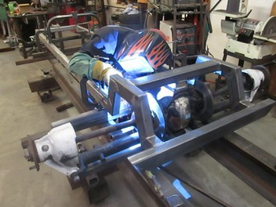
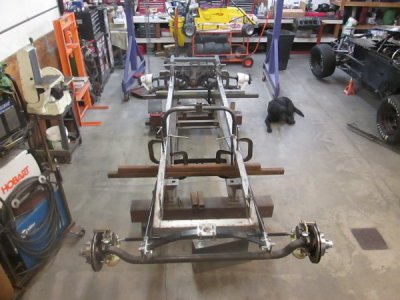
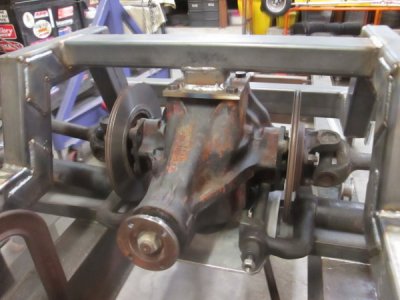
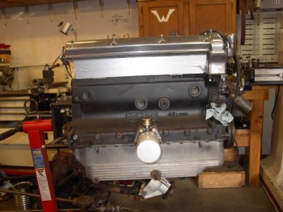
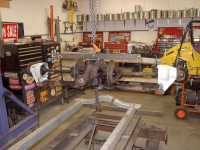
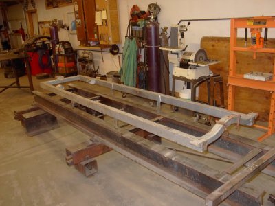
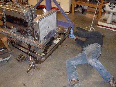
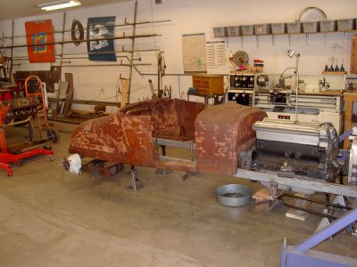
What do you get when you mix a 1968 Jaguar (pronounced jag you are in British) with a 1967 E-type independant rear suspension, fold it into a 20 year old home made frame, add an aftermarket radiator and front end, and top it with a 90 year old Model - T body? A lot of fun and time well spent with a neighbor. We're finished with the mock-up and I'm now working on the motor mounts.


- Joined
- Sep 2, 2013
- Messages
- 5,099
I reckon that would be a Jags"T"er. Seems historically It's usually about sticking an American V8 in a light weight British body ( have one of those in the works myself ). Pretty cool going the other way around. I've always liked the look of the inboard discs, but it seems there were issues with the diff and caliper seals going away from the heat transmitted by braking and exhaust routing. The exhaust routing should be an easy fix. A cross-member with a 3/16" wall tube section to keep exhaust outboard, away from the rotors, and it seems there was a fix for the rotors too, but I can't recall exactly what it was. Rotor hub material maybe. Cheers, Mike
- Joined
- Nov 19, 2014
- Messages
- 991
i don't know what we're going to do with the exhaust, the big challenge will be mounting the rear end and getting it to work right, I don't think the inboard discs heating up will be a problem, this is a cruiser, not a racer, check out the thread Rat Rod Lakes Pipe, thanks
- Joined
- Nov 19, 2014
- Messages
- 991
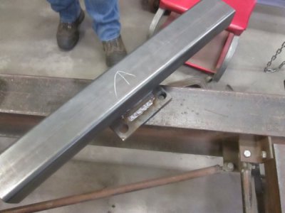
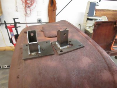
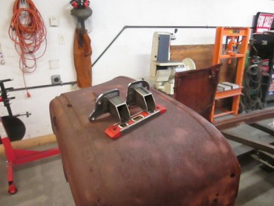
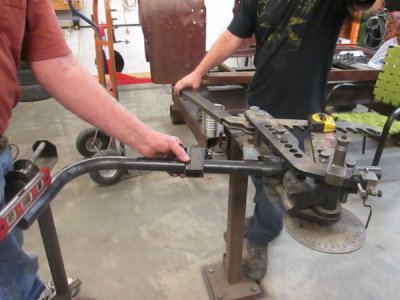
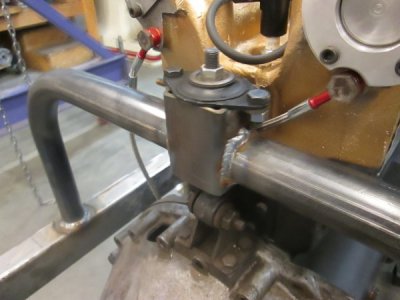
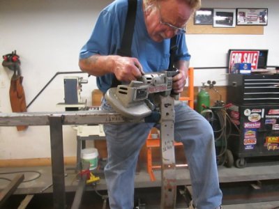
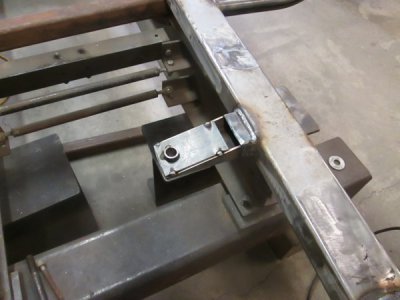
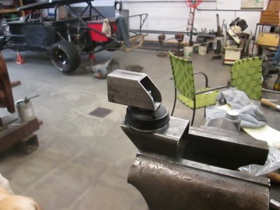 Here's the front motor mounts, keep it simple, the upper mounts, before and after me and my die grinder, and installed. Bending the mid mount, Bill wanted to use the OEM isolator so I had to build an adapter, it looks a little "klunky" but it duplicates a structure in the E-Jag cowl. the next logical step is the transmission mount but we're waiting on parts so it's on the jig for some surgery, the last picture is of the radius rod mount
- Joined
- Nov 19, 2014
- Messages
- 991
- Joined
- Jun 20, 2016
- Messages
- 346
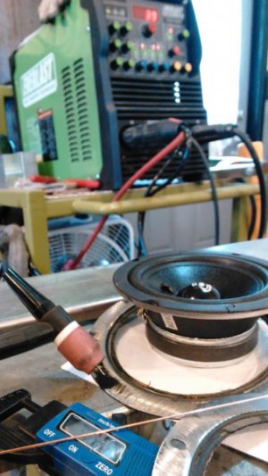
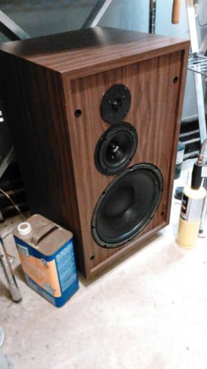
Welded a speaker... huh ? Why ? I got a nice pair of 1980's Cerwin Vega speakers on garbage day a while back. They needed woofers, no prob...there were high quality woofers available (bought Dayton 295-120) and I had some spare tweeters that were for a set of reference monitors. Problem was that I could not find a good quality 6" midrange to fit this cabinet. The 5-1/4" mid in the pic and video got very good reviews but it didn't fit the hole in the cabinet. I was going to try and make a spacer, I cut the flange off the old mid speakers and was going to use it as a template. Angle grinder with cutoff wheel and zipped the steel flange off the oem Cerwin mid speakers , dropped the new 5-1/4" mids into that 6" flange disc and decided why not just weld them on. I'd like to say I planned it but it's just kind of how it went. This is around 35-40 amps , 1/16" tungsten, 0.045" 625 Filler wire . Quick zaps all the way around and it stayed just warm to the touch ....the big chill blocks did their job. First pic is the flanges to be welded on the new speakers. Second pic is them done.
Near end of the vid shows all the welds and the untouched cone and paper.
------------------------------------------------
---------------------------------------------------------
Near end of the vid shows all the welds and the untouched cone and paper.
------------------------------------------------


---------------------------------------------------------
- Joined
- Feb 19, 2016
- Messages
- 326
Welded a speaker... huh ? Why ? I got a nice pair of 1980's Cerwin Vega speakers on garbage day a while back. They needed woofers, no prob...there were high quality woofers available (bought Dayton 295-120) and I had some spare tweeters that were for a set of reference monitors. Problem was that I could not find a good quality 6" midrange to fit this cabinet. The 5-1/4" mid in the pic and video got very good reviews but it didn't fit the hole in the cabinet. I was going to try and make a spacer, I cut the flange off the old mid speakers and was going to use it as a template. Angle grinder with cutoff wheel and zipped the steel flange off the oem Cerwin mid speakers , dropped the new 5-1/4" mids into that 6" flange disc and decided why not just weld them on. I'd like to say I planned it but it's just kind of how it went. This is around 35-40 amps , 1/16" tungsten, 0.045" 625 Filler wire . Quick zaps all the way around and it stayed just warm to the touch ....the big chill blocks did their job. First pic is the flanges to be welded on the new speakers. Second pic is them done.
Near end of the vid shows all the welds and the untouched cone and paper.
------------------------------------------------
View attachment 143492View attachment 143493
---------------------------------------------------------
Nice job! Why the inconel filler?
- Joined
- Jun 20, 2016
- Messages
- 346
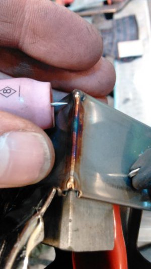
Thank you Sir ! I didn't know what kind of steel they used for speaker baskets and whether there was any compositional difference between the flange I cut off the speaker from 1980 and the new one . I know the 625 would wet in quick and smooth to whatever it is ...also i've got alot of 625 rod in 0.045 over here . Sure ER70 would have likely worked just fine but I knew the 625 would work . I figure it was a one shot deal with the pressed cardboard and the paper so close on the back side. The chill blocks are the biggest factor, they wick away heat from going toward the paper. I used the same chill blocks behind these 304 Stainless corners i welded, it's some kind of cover for something at my buddies work, 30 thou thick , no back purge , just alum chill blocks .Nice job! Why the inconel filler?
------------------------------------------------------
Last edited:


