Show Us Your Welding Projects!

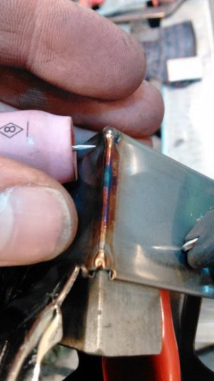
Nice fix, and welds. As I'm sure you have, I use the same basic method for mounting bosses on bike and car frames. Still waiting to get some time in on TIG. Have had all the gear for several yrs, just need to find the time. Mike
 
Nice fix, and welds. As I'm sure you have, I use the same basic method for mounting bosses on bike and car frames. Still waiting to get some time in on TIG. Have had all the gear for several yrs, just need to find the time. Mike

Thanks. Yes, I also use the same process for mounting items to tubular frames on bike and auto chassis. Back when I was fabricating sand drag chassis I especially used this process a lot.

Mike.
 
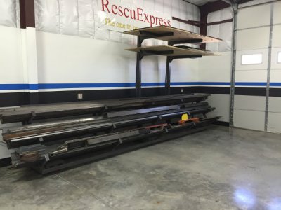
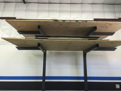
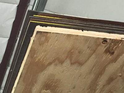
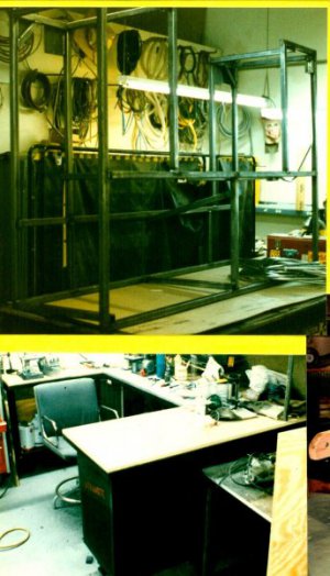
Update on the plate rack that was added on. It seems the truss design worked out well. The upper rack holds full 4' x 8' sheets of various gauge, I currently have 8 sheets resting on a 3/4" plywood sheet. The plywood sheets where laid-out prior to stacking. Two bold sharpie lines line up with the support arms (visible from the fork lift seat) for reinstalling stack once a sheet had been pulled.
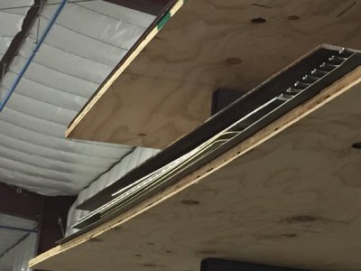
The lower sheet rack holds half sheets and various other remnants supported by plywood as well.
A simple solution for keeping the floor space clear. The lowest arms are 8' from the floor to keep drive through clear.
IMG_1798.JPG IMG_1799.JPG
IMG_1800.JPG IMG_1801.JPG
The old shop is now open for indoor parking.
Happy Fathers day to you dads!
 
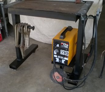
Here one just finish with a new $93.00 welder
All the parts are scrap iron The table is made from 9" x 15 channel legs are 4 x 2 x 1/4 tubing. Even the wheels and casters are from salvaged pile.
It a small table for small work I have in past years had table made 1" [25.4mm] plate do not want need table that size any more
I am only work on hobby work now so "keep it is small"

If you look at the right side were the MIG gun is hanging the gray tube side out for longer work.
The wheels and casters are set so a 4 x 4 can be place under the table legs for heavy work and pounding.

Dave


welding bench from scrap Aug 2016.jpg
 
Last edited:
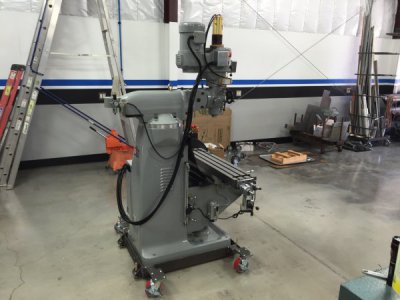
Made a rolling mill base for a friend, the design worked out well so far, but the real test will be when we move the machine to his shop.
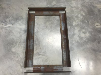
Main frame; 3/8" x 4"x4" angle iron.
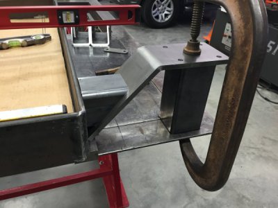
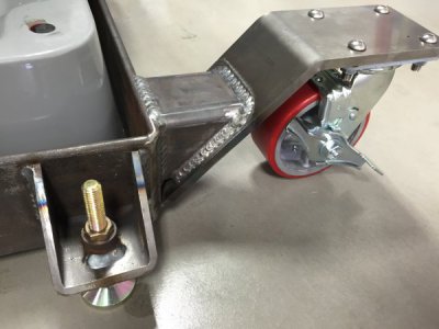
Castor mount plates; 3/8"x4" CR flat bar
Castor supports; 1/4"x3"x3" structural tubing
Leveling feet brackets; 1/4"x3"x3" cut at 45º
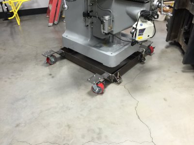
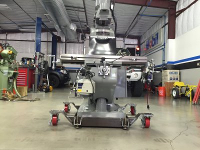
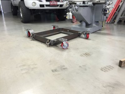
The design is a cantilever castor affording a wide base for rolling the mill from trailer to shop. We plan on using a Drop deck trailer for the move and his driveway is quite steep so I wanted to have a decent foot print to keep the machine stable while rolling.
The iron worker notched the corner joints in two bites, I wanted a strong joint so a miter joint was not used as this would have only given an 8" weld. The notched joint style provides 12" of weld per joint.
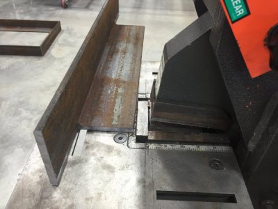
IMG_0018.JPG IMG_0019.JPG
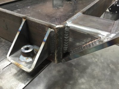
The CR castor plates where broken to 22.5º to end up parallel with the ground once they where welded to the 45º cut on the structural tubbing.
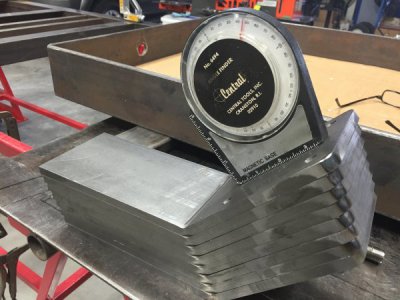
IMG_0043.JPG IMG_0052.JPG
The leveling feet where drilled to 11/16" and a piece of 3/4" round bar was turned to index into the hole of the bracket. The round bar was also drilled/tapped for the leveling feet (1/2"-13)
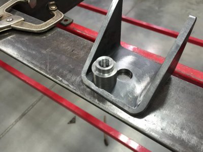
IMG_0053.JPG
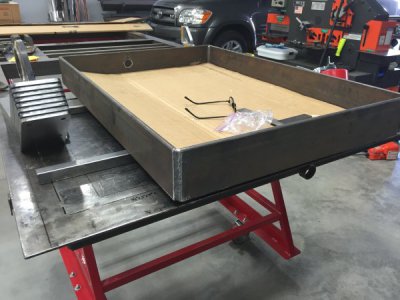
Prior to welding the frame, we set the mill onto a large piece of cardboard to trace the base and locate the mounting holes. A long custom made transfer punch was turned for this and the time spent was wort it to locate the holes. The template also helped with ensuring correct spacing to avoid the large radius found on the inside corners of the thicker angle iron.
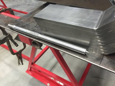
IMG_0044.JPG
Before welding the frame the template was use to transfer the mounting holes allowing us to drill/tap two sections of angle iron. The welding table was marked allowing us to verify squareness and correct spacing. The hole towards the back of the frame is for the coolant drain plug (also drilled prior to welding frame).
IMG_0045.JPG
The frame will be 1" off the ground once castors are mounted. Hopefully enough space to allow us to transition from the trailer to the floor.
IMG_0055.JPG
All vertical joint where welded up hill for decent penetration. The Miller 350P was set to 475IPM and skip welding was used to control distortion.
IMG_0064.JPG
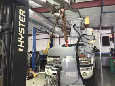
The test fit....I was nervous as I was alone for the pick, but with a come-along and fork lift,I was able to pick the mill up and keep her level.
IMG_0067.JPG
IMG_0069.JPG
Fit like a glove : )
IMG_0070.JPG IMG_0072.JPG
The leveling feet took the load off the castors with little effort using a 8" crescent wrench.
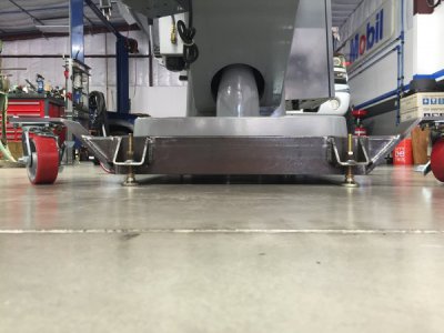
IMG_0074.JPG
IMG_0077.JPG
The last photo illustrates the castor clearance while swiveling 360º with about 3/16" clearance at its closest point.
A fun project and for a cool fellow member. Mark spent time assisting me with the build and was helpful. I'm sure he can't wait to get her home and start milling.
Tomorrow will be prime and paint.
Thanks for looking!
Turn and burn...
Paco
 
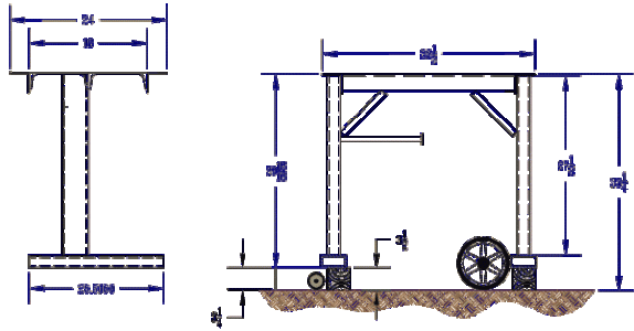
Drawing of welding bench

welding-bench-Drawing.gif

Here one just finish with a new $93.00 welder
All the parts are scrap iron The table is made from 9" x 15 channel legs are 4 x 2 x 1/4 tubing. Even the wheels and casters are from salvaged pile.
It a small table for small work I have in past years had table made 1" [25.4mm] plate do not want need table that size any more
I am only work on hobby work now so "keep it is small"

If you look at the right side were the MIG gun is hanging the gray tube side out for longer work.
The wheels and casters are set so a 4 x 4 can be place under the table legs for heavy work and pounding.

Dave


View attachment 133639
 

Attachments

  • welding bench Drawing.pdf
    11.7 KB · Views: 4
Back
Top