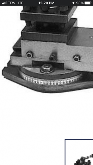
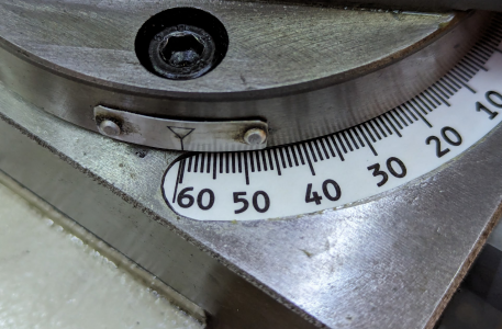
Replacement G0709 compound index plate

Aha! That's not in the parts list in my manual. Thank you!


Even a good FFF/FDM 3D printer (the melty plastic kind) won't produce a good result here, speaking as someone who has 3D printed plenty of text including on a reasonably high-precision printer (good enough to print working threads). You might get a good result from an SLA printer (cured resin type), but many of those are too small.


Could print them in reverse on a transparency, and then glue the transparency upside down to metal to protect the markings?

Print them in reverse, but also inverted (mirror image and reversing black and white) on transfer paper and use it as a mask for acid etch?


In my case, I scanned the plate when it was removed, next to a scale, used the scale to validate the dimensions of the 600dpi scan, then used three-point circles on the curves to find a circle.

Then I realized that I could measure the diameter of the circular features of the t-nut track and the offsets to get precise diameter for the curves of the plate. That was gratifyingly close to my first approach with the scanner. While I haven't yet manufactured it, I have reasonable confidence in the result. (If it's a little bit off, it's just tweaking a few constraints in the model.)
I don’t have anything that I’m aware of that I can do anything you recommended. I don’t know anybody with any 3-D printing or laser printing skill sets. There is a local place that will do laser engraving, but I still would need to find the correct diameter steel piece and I’m going to guess I’m going to need to know how much space in between each mark there needs to be. Unless the laser engravers software can figure that out.

I’m all very new to this, just finding material to be a struggle.

Currently, my compound the degree scale is just a flat tape around the outside, circumference of the compound body. Heck if I can find somebody confident with a laser engraver, I would just have them transfer what is on the tape now onto the actual steel body of the compound3F63AFF5-2717-455B-8100-0EA20618DC68.png
 
A stick on scale seems like a really bad idea! My lathe has a stamped? engraved? scale but viewing it is awkward at best. And judging it to .9° not going to happen. Not that it matters since I have no use for a 29.9° setting.
Could you setup a dial indicator on the compound and with a bit of trig, index the compound around a degree at a time as you stamped the marks by attaching a guide to the compound?
 
The G0709 has a milled slot to hold the stick-on scale, which is a pretty tight fit. But it's not going to give you tenths of a degree.
 
I wonder if I can have my wife give it a try with her laser engraver... using the old plate to play/practice with... hummm

I have updated the SVG file to be better for laser engraving. I fixed the line joins and text.

What kind of laser does she have? Blue LED or CO2 or fiber?

For marking with a CO2 laser, you want something like cermark, or maybe mustard.

Some of the new high-power LED lasers with non-spherical optics are reported to be able to mark metal.

A fiber laser could directly etch the metal deeply.

You can also paint it with a mask, laser-etch the mask, and then acid-etch the plate where the mask has been etched away.

Lots of possibilities.

Right now the SVG is just black. There are many thousands of paths in the export, which wouldn't be true if this had been authored initially in inkscape as an SVG. If I had done it that way, it would be easier to mark red for vector cut and red for vector engrave. But the way it is set up all the lines are black for raster engrave as K40Whisperer uses, and they aren't separated by layer as Lightburn and Meerk40t would use to differentiate modes. So if I were doing it as it stands now, I would raster engrave the whole thing, then use the outline to cut it to size, leaving the laser-marked ticks and numbers.

I realized I can't easily identify the 0 tick mark any more on my damaged index plate, so I printed this out, laminated it, cut it out, and put it in place. Much better! It won't survive the first time acetone gets on it, but then neither did the original.

So I also uploaded a PDF file that you can print easily.

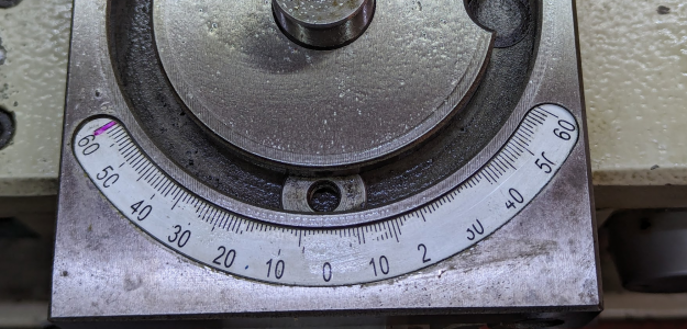
Here's the metal plate with my colored reminder of the general vicinity of threading, and the 0 not obvious:

1706065415711.png

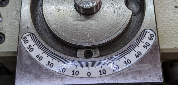
By contrast, here's the laminated version which for now I've just set in the slot on top of the original:

1706065495536.png

The glare isn't a problem in practice because it moves as I move around, and once the compound is installed, it masks the lights that were reflecting anyway:

1706065549734.png
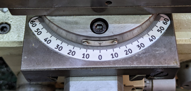
Here it is set up for threading:

1706065597024.png
 
I have updated the SVG file to be better for laser engraving. I fixed the line joins and text.

What kind of laser does she have? Blue LED or CO2 or fiber?

For marking with a CO2 laser, you want something like cermark, or maybe mustard.

Some of the new high-power LED lasers with non-spherical optics are reported to be able to mark metal.

A fiber laser could directly etch the metal deeply.

You can also paint it with a mask, laser-etch the mask, and then acid-etch the plate where the mask has been etched away.

Lots of possibilities.

Right now the SVG is just black. There are many thousands of paths in the export, which wouldn't be true if this had been authored initially in inkscape as an SVG. If I had done it that way, it would be easier to mark red for vector cut and red for vector engrave. But the way it is set up all the lines are black for raster engrave as K40Whisperer uses, and they aren't separated by layer as Lightburn and Meerk40t would use to differentiate modes. So if I were doing it as it stands now, I would raster engrave the whole thing, then use the outline to cut it to size, leaving the laser-marked ticks and numbers.

I realized I can't easily identify the 0 tick mark any more on my damaged index plate, so I printed this out, laminated it, cut it out, and put it in place. Much better! It won't survive the first time acetone gets on it, but then neither did the original.

So I also uploaded a PDF file that you can print easily.

Here's the metal plate with my colored reminder of the general vicinity of threading, and the 0 not obvious:

View attachment 475490

By contrast, here's the laminated version which for now I've just set in the slot on top of the original:

View attachment 475491

The glare isn't a problem in practice because it moves as I move around, and once the compound is installed, it masks the lights that were reflecting anyway:

View attachment 475492
Here it is set up for threading:

View attachment 475493
I would not mind moving my scale to that location.
 
I have updated the SVG file to be better for laser engraving. I fixed the line joins and text.

What kind of laser does she have? Blue LED or CO2 or fiber?

For marking with a CO2 laser, you want something like cermark, or maybe mustard.

Some of the new high-power LED lasers with non-spherical optics are reported to be able to mark metal.

A fiber laser could directly etch the metal deeply.

You can also paint it with a mask, laser-etch the mask, and then acid-etch the plate where the mask has been etched away.

Lots of possibilities.

Right now the SVG is just black. There are many thousands of paths in the export, which wouldn't be true if this had been authored initially in inkscape as an SVG. If I had done it that way, it would be easier to mark red for vector cut and red for vector engrave. But the way it is set up all the lines are black for raster engrave as K40Whisperer uses, and they aren't separated by layer as Lightburn and Meerk40t would use to differentiate modes. So if I were doing it as it stands now, I would raster engrave the whole thing, then use the outline to cut it to size, leaving the laser-marked ticks and numbers.

I realized I can't easily identify the 0 tick mark any more on my damaged index plate, so I printed this out, laminated it, cut it out, and put it in place. Much better! It won't survive the first time acetone gets on it, but then neither did the original.

So I also uploaded a PDF file that you can print easily.

Here's the metal plate with my colored reminder of the general vicinity of threading, and the 0 not obvious:

View attachment 475490

By contrast, here's the laminated version which for now I've just set in the slot on top of the original:

View attachment 475491

The glare isn't a problem in practice because it moves as I move around, and once the compound is installed, it masks the lights that were reflecting anyway:

View attachment 475492
Here it is set up for threading:

View attachment 475493
XTool F1 - she has engraved aluminum lids with it.

Will download and see if she can give it a try this weekend
 
@mcdanlj - where is the SVG file? and PDF? I did not see those attached to your post.
 
I gave up on attaching files after most of them were too large to post here. I keep pushing updates as I make changes to that location.

I missed that post. Got them now. Thank you.
 
Back
Top