

-
Welcome back Guest! Did you know you can mentor other members here at H-M? If not, please check out our Relaunch of Hobby Machinist Mentoring Program!
You are using an out of date browser. It may not display this or other websites correctly.
You should upgrade or use an alternative browser.
You should upgrade or use an alternative browser.
(PROBLEM SOLVED) PM940 CNC VFD spindle question
- Thread starter rodjava
- Start date
That is good news. It means the VFD is probably ok and the problem is else where. I will need to study the circuits a bit to proceed. We need to find where the wires coming to the VFD originate from. We know you have power in the box since your steppers are still working. However, I am on east coast and it is time for dinner. I will get back to you later tonight if possible.
Dave L.
Dave L.
If no power to the VFD, what should I be checking?The covers to these terminals as well as the ones to the motor at the bottom of the VFD fold down to allow you to look at them. See VFD manual page 1-8.
Dave,That is good news. It means the VFD is probably ok and the problem is else where. I will need to study the circuits a bit to proceed. We need to find where the wires coming to the VFD originate from. We know you have power in the box since your steppers are still working. However, I am on east coast and it is time for dinner. I will get back to you later tonight if possible.
Dave L.
Take your time and enjoy your meal. I'm going to sleep on it and take it up again tomorrow morning.
Rod in San Francisco
Hi Rod,
Maybe the circuit breaker to the VFD has tripped and you just did not catch it, or maybe it has failed.
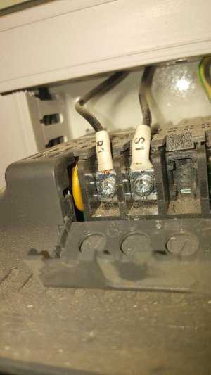
Looking at the Manual page 13 you will see the power feed to the VFD. On the upper left hand side you will see a circuit breaker, QM, that is feeding only the VFD. (By the way, just below this you will see the VFD that they actually call th Inverter DAP 03. Not for sure why and it is not shown in the parts list.) Anyway, the circuit breaker is adjustable from 5-8Amperes with a small red switch. I know you said you tried all of the circuit breakers but just in case lets try this one again. You did not provide a photo of it on your machine, but in the photos that you said were from a similar machine you will see it in photo pm940 cnc 1.jpg. It is in the row of circuit breakers (middle row) on the far left end and is small in this photo unless you enlarge the photo. It is labeled QM. It has a L2 and N2 feeding it with line power. The power to the VFD comes out the bottom and the wires are labeled R and S. You could measure the voltage between the R and S at this output and see if it has 220 VAC. If it does then the power is failing to get to the VFD from this point, but it is unlikely that both wires would break or come loose. QM has a rectangular red button and a grey button. When the Red button is all the way out and the grey button is all the way in (flush to the surface) the breaker is conducting and provides power to the VFD. I suggest you check it, push the buttons in and out a couple of times, if you are uncertain if it is engaged. You could also measure the voltage going into it to make sure that it is getting 220VAC at the L2and N2 wires.
The hook up for these things is a little strange. You will see in the drawing that the input has 3 terminals and that the one in the middle is connected to a wired that comes out the bottom right hand side. The way it works is the diagram is that the N2 goes connects at the right hand terminal and come out of the bottom on the right hand side. The wire is then connected from the bottom right hand side to the top center terminal. The bottom left and center terminals feed the R and S to the VFD. The reason for the right hand side is that when the current flows from the top right terminal through the device to the bottom right the device measures the current. If it is too large then the breaker trips stopping the current from exiting the bottom. If it is not too large (OK) then the power feeds out the bottom R and S lines on to the VFD.
I just went and looked at mine. On it the little red slide switch is set all the way to 8 Amperes. I have never had this thing trip on my machine, even when I once stalled the spindle motor and sheered off a pin on the inside.
I do not think this has anything to do with your issue, but by the way, it is not clear to me why our machines have such a very large black transformer at the top left of the CNC box. It seems like it is much larger than needs be and is breaker-ed below its capacity. The best I can tell it is only to provide 60 VAC power to the stepper motor amplifiers. This transformer is shown on the manual page 13 on the right hand side and is fuse with breaker FU4 at 10 Amps to power all of the stepper amplifiers. For some reason, upon powering up the controller with the green start button this FU4 trips and I have to open the door and reset it. It seems to be random as to when it occurs and I have not been able to figure out why it does this, but only on occasion. It is a pain because if you do not realize it has tripped and you use Mach3 to change the position the origin is lost. Mach3 does not know that the steppers are not working!
By the way if you want to see pictures of my machine look to my Feb 14th, 2019 post in the middle of the following thread.
 www.hobby-machinist.com
Good night
Dave
Maybe the circuit breaker to the VFD has tripped and you just did not catch it, or maybe it has failed.
Looking at the Manual page 13 you will see the power feed to the VFD. On the upper left hand side you will see a circuit breaker, QM, that is feeding only the VFD. (By the way, just below this you will see the VFD that they actually call th Inverter DAP 03. Not for sure why and it is not shown in the parts list.) Anyway, the circuit breaker is adjustable from 5-8Amperes with a small red switch. I know you said you tried all of the circuit breakers but just in case lets try this one again. You did not provide a photo of it on your machine, but in the photos that you said were from a similar machine you will see it in photo pm940 cnc 1.jpg. It is in the row of circuit breakers (middle row) on the far left end and is small in this photo unless you enlarge the photo. It is labeled QM. It has a L2 and N2 feeding it with line power. The power to the VFD comes out the bottom and the wires are labeled R and S. You could measure the voltage between the R and S at this output and see if it has 220 VAC. If it does then the power is failing to get to the VFD from this point, but it is unlikely that both wires would break or come loose. QM has a rectangular red button and a grey button. When the Red button is all the way out and the grey button is all the way in (flush to the surface) the breaker is conducting and provides power to the VFD. I suggest you check it, push the buttons in and out a couple of times, if you are uncertain if it is engaged. You could also measure the voltage going into it to make sure that it is getting 220VAC at the L2and N2 wires.
The hook up for these things is a little strange. You will see in the drawing that the input has 3 terminals and that the one in the middle is connected to a wired that comes out the bottom right hand side. The way it works is the diagram is that the N2 goes connects at the right hand terminal and come out of the bottom on the right hand side. The wire is then connected from the bottom right hand side to the top center terminal. The bottom left and center terminals feed the R and S to the VFD. The reason for the right hand side is that when the current flows from the top right terminal through the device to the bottom right the device measures the current. If it is too large then the breaker trips stopping the current from exiting the bottom. If it is not too large (OK) then the power feeds out the bottom R and S lines on to the VFD.
I just went and looked at mine. On it the little red slide switch is set all the way to 8 Amperes. I have never had this thing trip on my machine, even when I once stalled the spindle motor and sheered off a pin on the inside.
I do not think this has anything to do with your issue, but by the way, it is not clear to me why our machines have such a very large black transformer at the top left of the CNC box. It seems like it is much larger than needs be and is breaker-ed below its capacity. The best I can tell it is only to provide 60 VAC power to the stepper motor amplifiers. This transformer is shown on the manual page 13 on the right hand side and is fuse with breaker FU4 at 10 Amps to power all of the stepper amplifiers. For some reason, upon powering up the controller with the green start button this FU4 trips and I have to open the door and reset it. It seems to be random as to when it occurs and I have not been able to figure out why it does this, but only on occasion. It is a pain because if you do not realize it has tripped and you use Mach3 to change the position the origin is lost. Mach3 does not know that the steppers are not working!
By the way if you want to see pictures of my machine look to my Feb 14th, 2019 post in the middle of the following thread.
PM-940M-CNC
Got on one the last 940M-CNC's that PM produced. Its an all options unit with the 4th Axis, VFD, and auto oiler. Unit also came with a small coolant reservoir, pendant, and R8 drill chuck and shell mill, woohoo. Used a friends bobcat with forks to move the large crates off the semi trailer...
www.hobby-machinist.com
Good night
Dave
Dave,Hi Rod,
Maybe the circuit breaker to the VFD has tripped and you just did not catch it, or maybe it has failed.
Looking at the Manual page 13 you will see the power feed to the VFD. On the upper left hand side you will see a circuit breaker, QM, that is feeding only the VFD. (By the way, just below this you will see the VFD that they actually call th Inverter DAP 03. Not for sure why and it is not shown in the parts list.) Anyway, the circuit breaker is adjustable from 5-8Amperes with a small red switch. I know you said you tried all of the circuit breakers but just in case lets try this one again. You did not provide a photo of it on your machine, but in the photos that you said were from a similar machine you will see it in photo pm940 cnc 1.jpg. It is in the row of circuit breakers (middle row) on the far left end and is small in this photo unless you enlarge the photo. It is labeled QM. It has a L2 and N2 feeding it with line power. The power to the VFD comes out the bottom and the wires are labeled R and S. You could measure the voltage between the R and S at this output and see if it has 220 VAC. If it does then the power is failing to get to the VFD from this point, but it is unlikely that both wires would break or come loose. QM has a rectangular red button and a grey button. When the Red button is all the way out and the grey button is all the way in (flush to the surface) the breaker is conducting and provides power to the VFD. I suggest you check it, push the buttons in and out a couple of times, if you are uncertain if it is engaged. You could also measure the voltage going into it to make sure that it is getting 220VAC at the L2and N2 wires.
The hook up for these things is a little strange. You will see in the drawing that the input has 3 terminals and that the one in the middle is connected to a wired that comes out the bottom right hand side. The way it works is the diagram is that the N2 goes connects at the right hand terminal and come out of the bottom on the right hand side. The wire is then connected from the bottom right hand side to the top center terminal. The bottom left and center terminals feed the R and S to the VFD. The reason for the right hand side is that when the current flows from the top right terminal through the device to the bottom right the device measures the current. If it is too large then the breaker trips stopping the current from exiting the bottom. If it is not too large (OK) then the power feeds out the bottom R and S lines on to the VFD.
I just went and looked at mine. On it the little red slide switch is set all the way to 8 Amperes. I have never had this thing trip on my machine, even when I once stalled the spindle motor and sheered off a pin on the inside.
I do not think this has anything to do with your issue, but by the way, it is not clear to me why our machines have such a very large black transformer at the top left of the CNC box. It seems like it is much larger than needs be and is breaker-ed below its capacity. The best I can tell it is only to provide 60 VAC power to the stepper motor amplifiers. This transformer is shown on the manual page 13 on the right hand side and is fuse with breaker FU4 at 10 Amps to power all of the stepper amplifiers. For some reason, upon powering up the controller with the green start button this FU4 trips and I have to open the door and reset it. It seems to be random as to when it occurs and I have not been able to figure out why it does this, but only on occasion. It is a pain because if you do not realize it has tripped and you use Mach3 to change the position the origin is lost. Mach3 does not know that the steppers are not working!
By the way if you want to see pictures of my machine look to my Feb 14th, 2019 post in the middle of the following thread.
PM-940M-CNC
Got on one the last 940M-CNC's that PM produced. Its an all options unit with the 4th Axis, VFD, and auto oiler. Unit also came with a small coolant reservoir, pendant, and R8 drill chuck and shell mill, woohoo. Used a friends bobcat with forks to move the large crates off the semi trailer...
Good night
Dave
Tomorrow, I will check the voltage at the QM breaker. I will also try resetting it a few times as well. I think you are suggesting that the red tab on the QM breaker can be pushed in at different depths to control the amps from 5 to 8 amps. I did not know this. I will also take photos of my actual electronics. Perhaps you will notice something that is out of normal. Thanks again and have a great night.
Rod
Rod,
No, current is not set by the depth of the rectangular Red button. The current setting lever is very small and is located at the corner of the breaker in a black surround and is also red. It looks like a small lever and can be set to a value of current ranging from 5 to 8 A (Ampere). I think it has the letter "A" next to it standing for Amperes. When these types of breakers trip it is not uncommon that you have to reset it by first pushing the off button (rectangular red button pushed in is off) in all the way and then pushing the on button (rectangular grey button) in all the way which causes the red button to pop back out.....
Dave
- Joined
- Mar 26, 2018
- Messages
- 2,724
I am having a bit of a hard time following this thread so I'll post a set of tests. Feel free to skip any step that you have done already...
1. Read and understand what you are doing before you do it. Be safe
2. Set your meter to 500 V~
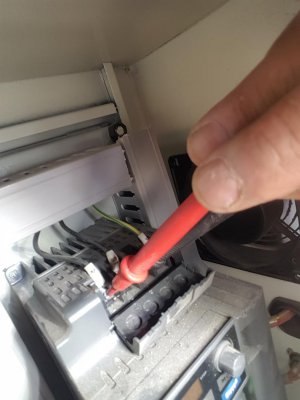
3. Place the black meter lead on COM and the red on V, ohm, mA (you have it right in the picture above)
4. Unplug the entire machine from the wall outlet. Lock out the connector if you can, if not just be extra safe.
5. Using your meter, measure the Line-to-Line voltage of the wall outlet (220VAC expected). Polarity is not important
6. Using your meter, measure the Line-to-Ground voltage of the wall outlet (2 measurements required, 110V expected for both). Polarity is not important
7. Set the knob on your meter to the audible continuity setting (two clicks clockwise from the 500V~ setting)
8. With the machine unplugged, measure continuity between the L1 prong of the plug which goes to the wall and the terminal "R" on the top of the drive (beep expected)
9. With the machine unplugged, measure continuity between the L2 prong of the plug which goes to the wall and the terminal "R" on the top of the drive (beep not expected)
10. With the machine unplugged, measure continuity between the L1 prong of the plug which goes to the wall and the terminal "S" on the top of the drive (beep not expected)
11. With the machine unplugged, measure continuity between the L2 prong of the plug which goes to the wall and the terminal "S" on the top of the drive (beep expected)
12. With the machine unplugged, measure continuity between the GND prong of the plug which goes to the wall and the terminal "R" on the top of the drive (beep not expected)
13. With the machine unplugged, measure continuity between the GND prong of the plug which goes to the wall and the terminal "S" on the top of the drive (beep not expected)
14. With the machine unplugged, measure continuity between the GND prong of the plug which goes to the wall and the terminal "GND" on the top of the drive (beep expected)
At this point I expect a few tests to have failed. Your notes state that the drive does not power up, so I do not expect that test 8 or test 10 will be successful. From what I can tell, there are a few components that sit between the VFD and the line power. These are the line reactor (square silver box) and a circuit breaker (unsure which one it is...). We need to test those.
15. With the machine unplugged, measure continuity between the Line side of the filter (terminal L) to the terminal "R" on the top of the drive (beep expected)
16. With the machine unplugged, measure continuity between the Line side of the filter (terminal L) to the terminal "S" on the top of the drive (beep not expected)
17. With the machine unplugged, measure continuity between the Line side of the filter (terminal N) to the terminal "S" on the top of the drive (beep expected)
18. With the machine unplugged, measure continuity between the Line side of the filter (terminal N) to the terminal "R" on the top of the drive (beep not expected)
Next I need you to trace the wire back from the Line side of the line filter to whichever circuit breaker feeds it. Please report which breaker it is. Also report the wire labels if possible.
With that information, I will give you some more tests to execute which will test if the circuit breaker is functioning properly. If all that works we will apply power and do similar checks again to determine why power is not reaching your drive.
All these tests are conducted with the machine unplugged. I am trying to do this to keep you safe while you work.
-Mike
1. Read and understand what you are doing before you do it. Be safe
2. Set your meter to 500 V~
3. Place the black meter lead on COM and the red on V, ohm, mA (you have it right in the picture above)
4. Unplug the entire machine from the wall outlet. Lock out the connector if you can, if not just be extra safe.
5. Using your meter, measure the Line-to-Line voltage of the wall outlet (220VAC expected). Polarity is not important
6. Using your meter, measure the Line-to-Ground voltage of the wall outlet (2 measurements required, 110V expected for both). Polarity is not important
7. Set the knob on your meter to the audible continuity setting (two clicks clockwise from the 500V~ setting)
8. With the machine unplugged, measure continuity between the L1 prong of the plug which goes to the wall and the terminal "R" on the top of the drive (beep expected)
9. With the machine unplugged, measure continuity between the L2 prong of the plug which goes to the wall and the terminal "R" on the top of the drive (beep not expected)
10. With the machine unplugged, measure continuity between the L1 prong of the plug which goes to the wall and the terminal "S" on the top of the drive (beep not expected)
11. With the machine unplugged, measure continuity between the L2 prong of the plug which goes to the wall and the terminal "S" on the top of the drive (beep expected)
12. With the machine unplugged, measure continuity between the GND prong of the plug which goes to the wall and the terminal "R" on the top of the drive (beep not expected)
13. With the machine unplugged, measure continuity between the GND prong of the plug which goes to the wall and the terminal "S" on the top of the drive (beep not expected)
14. With the machine unplugged, measure continuity between the GND prong of the plug which goes to the wall and the terminal "GND" on the top of the drive (beep expected)
At this point I expect a few tests to have failed. Your notes state that the drive does not power up, so I do not expect that test 8 or test 10 will be successful. From what I can tell, there are a few components that sit between the VFD and the line power. These are the line reactor (square silver box) and a circuit breaker (unsure which one it is...). We need to test those.
15. With the machine unplugged, measure continuity between the Line side of the filter (terminal L) to the terminal "R" on the top of the drive (beep expected)
16. With the machine unplugged, measure continuity between the Line side of the filter (terminal L) to the terminal "S" on the top of the drive (beep not expected)
17. With the machine unplugged, measure continuity between the Line side of the filter (terminal N) to the terminal "S" on the top of the drive (beep expected)
18. With the machine unplugged, measure continuity between the Line side of the filter (terminal N) to the terminal "R" on the top of the drive (beep not expected)
Next I need you to trace the wire back from the Line side of the line filter to whichever circuit breaker feeds it. Please report which breaker it is. Also report the wire labels if possible.
With that information, I will give you some more tests to execute which will test if the circuit breaker is functioning properly. If all that works we will apply power and do similar checks again to determine why power is not reaching your drive.
All these tests are conducted with the machine unplugged. I am trying to do this to keep you safe while you work.
-Mike
Hi Mike,
Rod established that there is no power at the VFD input (R-S terminals), but that there was power available for the steppers (steppers would move the table when the spindle would not turn). This simplifies a lot. So I identified the breaker, QM, that is feeding the VFD line power and Rod was going to test it and if it looks un-tripped then measure the line voltage to it to see if it is getting power. It is an adjustable breaker, 5 to 8 Amp, and the spindle motor is 1.5KW so I expect that the setting needs to be near max, 8Amp.
Rod is registered as being in CA so he probably has not returned to all of this yet. You are in Cleveland and I am in Pittsburgh so we are up.
Dave