I am sorry Rod, I assumed you had a little more of an electrical background. Yes, always be safe. If you are not for sure then ask. So for the input power and the lines to the motor we are measuring AC voltage not DC. So the meter should be set to 500 VAC. The smaller terminals all have low voltage DC at them. So you would use the DC scales and the voltages we are trying to measure are under 25 volts. The Voltages at the Relays inputs (coils) will most likely be 24 VAC or 60VAC so a 100 volt AC scale would be safe. The output from a relay can be what ever is presented to its input.
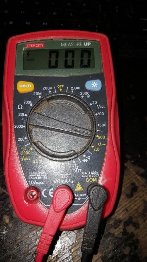
For AC measurements there is no difference between the black and the red lead. For DC measurements if red lead should be plugged into the red hole (+) and the black lead into the black hole(-). Then when one connects the red lead to a positive DC voltage he gets a positive reading. (what kind of VOM do you have? Is it a DVM or an old fashioned needle style?)
So let me see if I have this correct. I have gotten a little lost in the process. So let me set up some steps.
1) When the computer is turned off, but the Mill power switch is on does the VFD LED display light up? (yes or no)
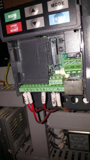
2) If yes, there is power to the VFD. But you could still measure the inputs to the VFD to see if the power is of quality. I assume you are running with a house hold circuit of 220 Volts 1 phase. If so, then you should set the meter to 500 Volt AC and measure between terminals R and S (L1 and L2) on the VFD. If you do not measure round 220 volts then the power is poor and might not run a motor.
3) If the VFD is on and the 220 input is good, then look at the VFD and see if there is a light on that says FW. If so, then it is telling us that there is an input signal at the MI1 control input, but lets check. Put the VOM meter on a DC scale to check for at least 24 volts DC and then connect the Red lead on the KA1 input which is the MI1 VFD control screw terminal while putting the black lead on the terminal called DCM (page 2-2 of VFD manual) which I think is the wire labeled (111) . You should read 24 volt DC or about this amount. If so the KA1 is working ok.
4) Assuming the power is of quality, and the VFD is displays are working then we need to check the control signals when Mach3 is controlling things. For this we have to turn on the computer and run Mach3.
( will continue while you confirm the above)