

-
Welcome back Guest! Did you know you can mentor other members here at H-M? If not, please check out our Relaunch of Hobby Machinist Mentoring Program!
You are using an out of date browser. It may not display this or other websites correctly.
You should upgrade or use an alternative browser.
You should upgrade or use an alternative browser.
POTD- PROJECT OF THE DAY: What Did You Make In Your Shop Today?
- Thread starter wachuko
- Start date
- Joined
- Dec 20, 2021
- Messages
- 868
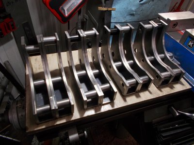
Wrapped up 4 pair of lower link mounts for the Cat 0 project.
Need to get 'em painted now.
Looks good!
How did you cut the radius/curve. Looking at tool marks guessing fly cutter, or maybe CNC???
- Joined
- Mar 22, 2022
- Messages
- 342
Good points!I agree that it is a great learning experience, and I do see it as an important set-up proof for the Clausing after your total tear-down. But on a light lathe, how does one separate the effects of deflection from the conditions of alignment? I would think that two collars on centers would tell you that the tool tip tracks the axis, even if it doesn't account for alignment. Maybe watching a test indicator on the end of the work as a cut is made would give you a deflection value to help keep account. I dunno, it's an interesting metrology question that gets more challenging to address as machines get smaller.
Decided to try the two collar approach.
Did not have much luck attempting to measure deflection.
So
Applied some marker, honed the tool and did a couple cuts to establish a new base followed by a .0005 cut.
Measured the chuck side at .9470
Far end at .9478
.0006 larger on the far end then when turned as a contiguous part after aligned.


Back to the question of deflection or alignment as root cause.
Only way I can see forward is to do a series of spring passes, mark ups and measurements.
Four passes later
#1 chuck side .9470
far end .9476
#2 chuck side .9470
far end .9475
#3 chuck side .9470
far end .9473
#4 chuck side .9470
far end .9473

Spring pass #4 was just sharpie ink

Not very scientific and doubtful that NASA will be reaching out to me any time soon.
But good hands on and have some faith that things are aligned now.
Will see how it goes when I chuck up a 3/4 X 3 inch 12L14 rod next.
- Joined
- Feb 25, 2021
- Messages
- 3,129
This time change is killing me.
More fiddling (and making a mess!) on the crane project. The driveshaft is square, because a handwheel drive will move the bridge. But that handwheel will be able to move independently of the chain fall carriage along the bridge. Since the drive handwheel moves, a slip fit 'drive mechanism' (No idea what to call it, but it drives the square shaft...) needs to slide along the driveshaft. I couldn't easily find any receiver tube for the 2" square tube so made that a long bit ago. Finally adding the sprocket and support for the 80mm ID bearing that supports drive mechanism. That probably doesn't make any sense, yet. But it will as more hardware gets done.
View attachment 481993 View attachment 481992
Purple box is a worm gear, w/ a roller chain from that to the square tube drive?
- Joined
- Dec 20, 2021
- Messages
- 868
Yep, that's the idea.Purple box is a worm gear, w/ a roller chain from that to the square tube drive?
It still remains to be seen if it actually works, once all the hardware is built.
- Joined
- Dec 20, 2021
- Messages
- 868
Do you have a tenths indicator?Back to the question of deflection or alignment as root cause.
If you measure both ends, then mount an indicator in the tool holder and see what the indicator says.
If the indicator agrees with radius of the part or not, that should help you sort out deflection vs. alignment. The size of each turned section doesn't have to match each other. Just mark out the radius on paper and see how the indicated measurement agrees.
This will probably help you reveal all sorts of neat things to think about when aligning that lathe...
")
This time change is killing me.
More fiddling (and making a mess!) on the crane project. The driveshaft is square, because a handwheel drive will move the bridge. But that handwheel will be able to move independently of the chain fall carriage along the bridge. Since the drive handwheel moves, a slip fit 'drive mechanism' (No idea what to call it, but it drives the square shaft...) needs to slide along the driveshaft. I couldn't easily find any receiver tube for the 2" square tube so made that a long bit ago. Finally adding the sprocket and support for the 80mm ID bearing that supports drive mechanism. That probably doesn't make any sense, yet. But it will as more hardware gets done.
For right now, I'm making this.
View attachment 481979
It's made from a homemade square tube with some 3/8" plate welded on. To support the thing in the lathe, an insert needs to be made to just lightly press into the square tube. So more cutting and milling, and messing up the little mill.
View attachment 481978
Took a good hour to get everything running true. I really loathe setting up square tube a 4 jaw chuck. It's not hard, just tedious. Here's the parts, just before heading to the lathe.
View attachment 481981
And finally, making a few chips. Interrupted cuts, cuts through weld, being driven form the far end and supported with a live center made me nervous. Just took light passes, hand feeding everything. Stopped 40 thou shy of the final cut. Since a bearing fits over this, figured letting it cool for the night before cutting to final dimension wouldn't be a bad idea.
View attachment 481980
Edit: Here's a bit more context into how this fits the drive wheel mechanism. Not everything in the gold colored support carriage is fleshed in there yet. Some additional rollers are missing from these views.
View attachment 481993 View attachment 481992
Have you seen the crane build on RC Groups? I will go look for it.
1:8.5 Scale Manitowoc 18000 Lift crane - Page 30 - RC Groups
Page 30-Build Log 1:8.5 Scale Manitowoc 18000 Lift crane The Builders Workshop
- Joined
- Dec 20, 2021
- Messages
- 868
Wow, that's quite the project!1:8.5 Scale Manitowoc 18000 Lift crane - Page 30 - RC Groups
Page 30-Build Log 1:8.5 Scale Manitowoc 18000 Lift crane The Builders Workshopwww.rcgroups.com
This is nothing that complex.