Mill Spindle Light

Doing it that way is not a great idea, though a lot of inexpensive electronic devices do it that way.

The problem is that you need to use a resistor that will drop the proper amount of voltage when the current for all of the LEDs is being drawn through it. Then if any of the LEDs burn out, the current through the resistor will be less, so the voltage dropped will be less, meaning the remaining LEDs will see a higher voltage. To some extent , this higher voltage will cause a greater current through each LED, and can cause more of them to fail, making the situation worse.

Also, if all the LED are not identical (and they aren't) some will draw more current than others. Better to put all the LEDs in series with a single current-limiting resistor and a higher voltage supply. Much simpler and more efficient.
 
http://www.jameco.com/webapp/wcs/stores/servlet/Product_10001_10001_2174881_-1 is the link for jameco white led's. Depending on the DC voltage, order appropriate resistor for current of 20ma. If you use a 12 volt DC supply, the resistor should be between 600 and 625 ohms. Size the wattage of the resistor such that P (power) = I (current) X E (Voltage) if you use 30 LED's, use (0.020 watts (20 ma) X 30) X 12 volts = 7.2 Watts -> round up to 10 watt 600 ohm resistor.
Hope this helps - make sure that the 10 watt resistor is elevated or is on some type of heat sink, otherwise use a 1/2 watt 600 ohm resistor for each led. :confused::confused::confused:

There are a couple of problems with the calculations and resistor values shown above.

1) To size an LED resistor, you calculate the resistance to give the desired current using Ohm's Law, but you need to use the voltage across the resistor, NOT the supply voltage. All LEDs have an intrinsic voltage drop, and the drop for a white LED is usually about 3.4V. So when using Ohm's Law, you need to use (Supply voltage minus LED voltage), instead of just supply voltage. The 600 ohm resistor mentioned above would only let 20mA of current flow if it had the entire supply voltage across it.

Assuming a white LED with a voltage drop of 3.4V, you would calculate the proper resistance to give 20mA of current using R(resistance)=V(volts)/I(current), or R=(12V-3.4V)/.02, which gives a resistance value of 430 ohms.

Using a 600 ohm resistor in this circuit would give a current of I(current)=V(volts)/R(resistance), or I=(12V-3.4V)/600, or only 14.3mA. Note that this would probably work OK, as most modern LEDs will be nearly as bright with 15mA of current as they will with 20mA of current.

2) If you use one resistor to drive all of the LEDs in parallel, you actually need to change both the resistance and the power rating from that used for a single LED.

So using the 430 ohm resistor as calculated above for (1) 3.4V LED with a 12VDC supply, we have the following values:
Vs(Supply Voltage)=12V
Vl(Voltage across the LED)=3.4V
Vr(Voltage across the resistor)=8.6V
I(current through the LED and the resistor)=20mA
R=430 ohms

If you tried to then change the circuit so that (1) 430 ohm resistor(of a higher power rating) was supplying current to (30) LEDs in parallel, I would increase to 20mA*30 or 600mA.

Drawing 600mA through a 430 ohm resistor would cause a voltage drop across the resistor of V=I*R or V=600mA*430 ohms, or 258V! Obviously, that will never be attainable with a 12V Supply.

If instead, you connected the LEDs in series, you could use use a single resistor to limit current to 20mA, but you would then need a power supply voltage of more than 3.4V * 30 or 102V. You would need to calculate the resistance value as above, using R(resistance)=V(volts)/I(current), where V was (Supply Voltage-102V). Assuming a 120VDC supply, R=(120-102)/.02 or 400 ohms. This resistor would need to have a power rating of 8V*.02A or .16watts, so a 1/2 watt, or even a 1/4 watt, unit would work.

This scheme has the disadvantage that if any of the (30) LEDs burns out, the entire string would go dark.


It is a much better idea to simply bite the bullet and use a proper current-limiting resistir for each LED. It will be much more reliable in the long run.
 
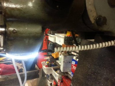
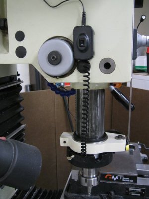
I really like the idea of using the coiled phone cable to extend and retract. I have my wire set so it is just long enough for the longest length of the spindle and find it is not in the way when retracted. But if done again I would use the phone cord. I don't have a switch yet but want to add one soon. Kind of a pain to have to plug the power supply in and out every time I use it. Might install the phone cable when I install the switch.

Thanks for the idea.
 
Dang, too small for the 4" quill on my Gorton 9J. I'll have to measure my 8.5D quill to see if these will fit on it.

Very cool lighting and thanks for posting the link Marcel.

I bought one of these
View attachment 69536
from:http://www.superbrightleds.com/more...adlight-accent-lights-with-t3-14-adapter/878/

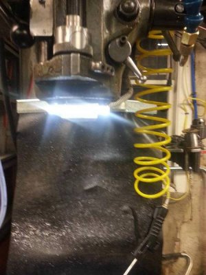
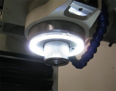
It comes with the protective dome already on it. The size is perfect for a Bridgeport or clone spindle.
I epoxied 4 small high power magnets to it. I spliced in a coiled telephone cord, so that it can move and stay out of the way when the spindle is extended. Grabbed a toggle switch that I canniballized from something. Scrounged a small plug-in transformer that I saved for just such a project. And voila...An awesome spindle light that's unobtrusive and gives off some excellent lighting, exactly where it's needed.
20140208_210056_zpsgufll3qj.jpg

20140208_210112_zpso3ajqyye.jpg

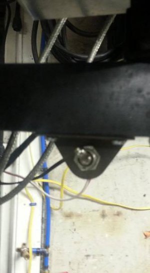
I mounted the toggle switch right below my DRO mount swing arm.

00233f71-095d-4c95-bcab-c3207cb4f43b_zps00602299.jpg

Thanks for the ideas guys. This is great!

PS: I don't have the patience for soldering in all those LEDs. Maybe it's my caffeine consumption...the hands jitter too much.:)) I had enough soldering, just soldering in the wire and switch connections.:whistle::phew:


Marcel
 
They sell bigger ones. You have to buy the dome seperately, but the domes are cheap. Check the site. When you scroll down the page of the different halo fixtures, the dimensions are towards the bottom.

Marcel
 
Thanks Marcel. Those are very cool and the coiled telephone cord is pure genius.
 
I got a little side tracked and built a building in the mean time. I hope to be back on track by next month... Being older with a few health conditions tends to keep me in the house when the temps are in the 10, 20 and 30s.... :(

Hope others are having warmer days.
 
My condolences and prayers go out to you.

I like the LED light - I'll be looking for one.
 
Here's mine....


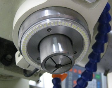
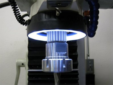
I decided to build one too after seeing the angel eye/halo LED that xalky used for his mill, thanks Marcel! The vendor he linked didn't have the size I wanted so I ordered it on ebay. I used a 90mm ring with 60 LEDs.


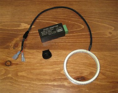
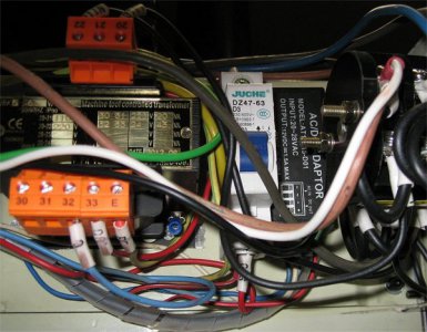
Here are the parts I used, the angel eye LED that I rewired, an AC to DC converter, & a lighted rocker switch.
Img_9153.jpg


I installed the AC to DC converter inside the control box which is being powered from the stock light's 24V circuit.
Img_9164.jpg


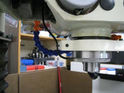
I choose the 90mm ring so it would fit just over the bottom ring on my quill. Had to remove just a bit of the ID to fit & it snaps right into place. Although I didn't need it I added a bit of double sided tape just in case. Couldn't have asked for a better fit!
Img_9178.jpg

Img_9185.jpg


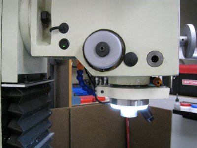
Installed the lighted rocker switch on one of the existing holes & the other hole for the wiring to the control box.
Img_9187.jpg

Img_9197.jpg


I'm pretty happy with it & I like the slim profile much better than the drill press quill LED unit that they sell. Thanks for the ideas everyone!

- - - Updated - - -

Oh & this is the one that I tried before installing this one. I didn't like it cause it was too bulky & the tint was too cool.

Img_8996.jpg

Img_9004.jpg
 
They sell bigger ones. You have to buy the dome seperately, but the domes are cheap. Check the site. When you scroll down the page of the different halo fixtures, the dimensions are towards the bottom.

Marcel


What do these require for a power supply
 
Back
Top