Let's talk , Cincinnati Toolmaster 1A and 1B

I do not, sorry.

I only recognized the building because I was just up there over the July 4th weekend. He's got a lot of stuff. Some good, some not so much. No prices on anything though and I hated asking, but when I did I could't believe the prices. Picked up 3 machines that day. Might have to go up there again once I clear out some space to set up the machines I already bought.


He had a huge horizontal Cincinnati outside under the carport but I didn't ask about it. I wanted to, but no real space for it.


If you got the machine for what he told me he usually get for vertical mills, you probably made out pretty good.

I bought it for $750 and have been doing some work on it . Everything works on it I am just making it work like it would over 50 years ago. Yea he usually has awesome prices. I also bought my rotary phase from him for about $100 less than you would normally pay. Nole is a good guy and I am thinking about popping in there tomorrow to speak with him about this panel because he will probably have an answer . There are a lot of machines I want from him . I also bought a war production grinder from him. There are some other things like a surface grinder , larger lathe, cold cut saw and so on . Maybe we will run into each other over there some time .
 
That's cheaper, he said he normally gets $900 for the verticals. I noticed that things got cheaper as I kept loading up. I think he's cheaper when he has a lot of inventory too.

I got a surface grinder from him when he was cleaning out a shop in Yorktown for $250 because he didn't want to drag it back with him.

He's got a few more machines I'd like to get too, but space is becoming an issue.

I don't get up there much, and no real plans to soon but you never know. The wife was upset because she couldn't go with me when I went. Maybe one rainy Saturday when we have nothing else to do.
 
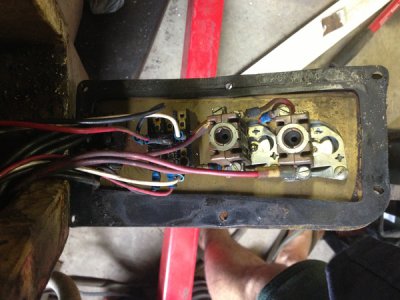
One confusion I'm having is my circuit interrupter and contactor/starter has L1-L2-L3-L4 now the schematics only show L1,2, and 3 so what is L4?

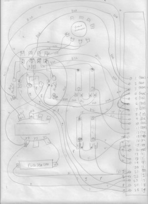
I have just completely drawn my own schematic of the existing panel to the exact detail . Now I am comparing it to the Cincinnati schematic .
Your contactor is basically a big relay with 4 contacts. 3 of the contacts control the 3-phase power to the motor(s). The 4th contact is used as a "hold-in" contact, which completes the coil circuit after the start button is released; that's probably your "L4" terminal on the contactor. I explained how all that works in post #17.

I'm not sure what your main question is. You have a wiring diagram. Did that come with the machine? Are you trying to check the wiring against the diagram, or what?

You pictures from post #46 aren't displaying and I can't get your PDF to load.

Cal

Cal I understand what the purpose of the contactor / motor starter is but other tool masters only have l1-l3 and on my circuit interrupter there is a L4 coming in and out as well . The L4 is also hooked up to the heater on the right of the contactor which is linked to the T4A (#4) terminal . Yes I was trying to match my machines wiring to the wiring diagram but its not a very old diagram for someone who isn't into electrical every day . They could have numbered the same numbers and letters as they wired into the machine . Anyways speaking with Mike on the phone shed a lot of light on what I need to do but it's still a bit fuzzy for me. I think I got a hold of my electrical engineer friend so hopefully he can sort this mess out tonight or tomorrow .

It does not look like the L4 is in series with the starter at all but maybe I don't exactly understand about the hold function. What would I hook up to L4 coming into the machine then?

All of the photos are working for me try going to

http://www.stellarsmithing.com/cincinnatiTM directly
 
I updated the schematic I drew as I left out a few things .

http://stellarsmithing.com/cincinnatiTM/IMG_7852.JPG

IMG_7852.JPG
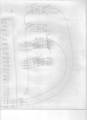
Here is the second half

http://stellarsmithing.com/cincinnatiTM/IMG_7853.JPG

IMG_7853.JPG

I have another schematic showing the start panel . I am uploading now after I do a few more things on it

Also since you are back in the thread cal maybe you can steer me in the right direction as far as purchasing a new starter or contactor.

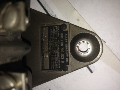
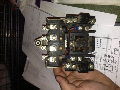
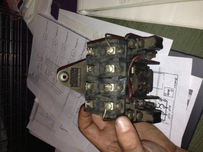
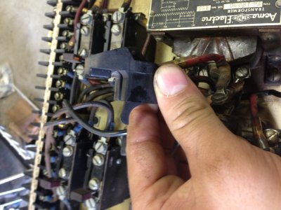
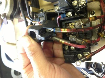
Here is some photos .

IMG_7849.JPG
IMG_7850.JPG
IMG_7851.JPG

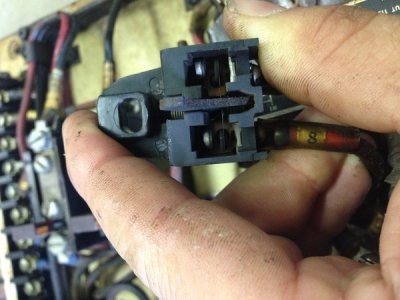
Here is that little switch on the contactor not exactly sure what it does but it has to do with the start and stop button. Wire #9 goes to the start button and wire #8 goes to the stop button #8 bypasses the coil on the contactor but #9 goes to the coil and then this switch
IMG_7834.JPG
IMG_7835.JPG
IMG_7836.JPG


I do have a start, stop and two toggles that I have traces the wires too .
IMG_7838.JPG
 
OK, what you've sketched does not match the wiring diagram that you posted, but that's no surprise. What you're doing in getting a wiring diagram is a good first step. I'm not at all surprised to find that there are a lot of wiring differences between your machine and another, similar machine. Van Norman millers are notorious for this. Don't get upset that your machine is a little different. I think you'll find that there are a fair number of similarities between your machine and the diagram.

The little switch that you ask about appears to be the "hold-in" switch. When the contactor closes, the lever on the switch closes it also, so it's closed any time that the contactor coil is energized. You should find that it's in parallel with the start button and in series with the coil circuit. When you press the start button you complete the coil circuit and energize the coil, causing the contactor to close. The hold-in switch is part of the contactor and closes when the contactor closes. Sometimes one of the contacts in the main bar is used for the hold-in function; contactors like your Allen-Bradley have a separate hold-in switch. The hold-in switch is in parallel with the start button, so that it bypasses the start button as soon as the contactor closes; without it the coil would loose power as soon as the start button was released. Does that make sense?

The diagram that you posted shows a 4-pole contactor, like the one that you have. The contact pair on the left side are used as the "hold-in" contacts; yours uses a separate hold-in switch.

What do terminals D1A, D2A, D3A and T4A, on the terminal strip at the right, connect to on the rest of the machine?

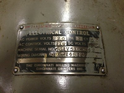
Usually the only time you see L4 on a machine is when you have one that's set up for two-phase power. 2-phase was used up in the Niagra Falls area for a period of time, I think up into the 50's and possibly beyond. Hopefully that's not what you have. Can you post a photo of the plate on the spindle motor?

What makes you think that you need another contactor?

Anyway, this looks pretty straight forward. Let me know if you want help figuring it out.

Cal
 
Cal I think this says it all

IMG_7864.JPG

It was originally 2 phase ...

I can't believe I didn't even pay attention to this. Now would be the time for me to be led by the hand .

So can I buy a three phase size 0 starter and use all the other components or is this all an issue?

Also in post #33 I have a video on YouTube which shows you exactly why I need a repeated or to replace the contactor. I don't know how I would fix it and can it be used with three phase? I'm not sure what went to the T4A that's why I was confused but it looks like the D1 D2 and D3 originally went to the spindle motor . The original spindle motor is long gone and someone had replaced it with a single phase 220v and just had a plug to it . It seems that it was being used as a drill press only. The original Fairbanks Morris shaper motor is on the rear of the overarm and it is a 3 phase motor. The table feed is a Baldor 3 phase industrial motor which doesn't believe to be original either .

I have retrofitted a 1hp 3 phase Bridgeport pancake motor for the spindle btw .

So lay it too me ? Where do we go from here? Is this freaking rare or what?
 
Cal tell me what 3 phase starter you think I should use ? Or what size I mean . I will try to find an old AB on eBay or something that is a 3 pole and then I will try my best to rewire using Mikes schematic . He gave me a schematic he made of his working mill and it is 3 phase and he has 4 different motors like me with a slight difference on the toggles .considering I will be hard wiring the machine into the panel with a breaker I don't see the need for the circuit interrupter which is missing the key anyways . So I say I can wore directly from the 3 phase panel into the Contactor/starter and then make sure everything is wired up for 3 phase . Does this sound like the best route?

Josh

What do you think of this?
http://bit.ly/18WkwZD

There is also this one.
http://bit.ly/137GCjS

According to the sizing chart the size 1 is good to 7.5 HP on 220v 3 phase

And according to the chart size zero is good for 3 HP although the one in my machine says good for 2 HP at 220v .

They are both cheap so should I go for the zero or the one? Can you go bigger and it be ok ?
 
Well sometimes I'm impatient so I bought this

http://bit.ly/18RB9lF

I guess there is no need for the larger than size 0 although I may buy the size 1 709 for future if I need to put larger motors on the mill or use for anything else I may have. I think I am finally understanding all of this. I guess a lot of it is a lack of confidence on my part which wants me to have some one reassure me that I'm doing it right before I blow my bank account on parts lol .
 
…It was originally 2 phase ...


Also in post #33 I have a video on YouTube which shows you exactly why I need a … to replace the contactor. …The original spindle motor is long gone and someone had replaced it with a single phase 220v and just had a plug to it. … The original Fairbanks Morris shaper motor is on the rear of the overarm and it is a 3 phase motor. The table feed is a Baldor 3 phase industrial motor which doesn't believe to be original either .

I have retrofitted a 1hp 3 phase Bridgeport pancake motor for the spindle …


… I will try to find an old AB on eBay or something that is a 3 pole and then I will try my best to rewire using Mikes schematic . He gave me a schematic he made of his working mill and it is 3 phase and he has 4 different motors like me with a slight difference on the toggles .considering I will be hard wiring the machine into the panel with a breaker I don't see the need for the circuit interrupter which is missing the key anyways . So I say I can wore directly from the 3 phase panel into the Contactor/starter and then make sure everything is wired up for 3 phase . Does this sound like the best route?

Josh
OK, so to summarize, the machine was originally 2-phase and has been extensively modified, probably including all new motors. There’s no way to know if the shaper is original to the machine, but that’s doubtful since you say that it’s 3-phase; I would expect an original shaper to be 2-phase as well. The control panel was wired for 2-phase but appears to be the same physical panel used for 3-phase machines. You now have 3-phase spindle, feed and shaper motors. The original contactor has a bad coil.

Note to the unfamiliar: 2-phase power is not to be confused with single-phase. It was in use in the Niagara Falls area in the first half of the 1900’s.

Given the above, I would pull all of the old wiring out of the panel and start fresh using the 3-phase wiring diagram from post #10:
panel wiring
starting circuit

I think that you’ll find that regardless of the start/stop and aux control panel switches, the control panel wiring will be pretty much as shown in the panel wiring diagram. I haven’t seen Mike’s schematic, so I can’t comment on it. But there’s a reason for everything on that panel and you are better off going with a factory wiring design than something else. You don’t know who bypassed what to get Mike’s machine working.

The starting circuit that you posted shows more circuitry above the starting circuit. Can you post the rest of it or e-mail a scan to me? (I'll send you an e-mail.)

The good news on your panel is: a) it’s the same basic panel used for 3-phase machines; b) your transformer has a 120 secondary; c) the panel was originally 220 Volts, so the heaters for all of the overloads are probably correctly sized (or were for the original motors); d) the heaters from the old contactor are the same series used by the replacement contactor that you bought. We’ll have to look at the rating plates for each motor and verify that the overload heaters for all of the overload devices are correctly sized for the new motors

If I understand correctly, the “circuit interrupter” is a safety switch of some type that cuts power to the panel when the door is opened. Is that the case?

I’m very familiar with the Allen-Bradley bulletin 709, size 0 contactor that you bought. It’s rated for up to 3HP on 220/240, so you don’t need a larger contactor. I see that the seller had 5 or so for sale; hopefully, the one you get also has a 120VAC coil, which is what you need. We’ll need to verify that the N22 heaters from the old panel are correct for the replacement spindle motor.

If the machine came with a fused disconnect panel, I would use it rather than wire directly to the breaker panel. Virtually any machine shop you go into you will find fused disconnects on every machine.

One issue that you will need to attend to is to make sure that the two phases used for the starting circuit are the real phases; you don’t want to use the artificial phase from the rotary phase converter in the starting circuit.

Cal
 
Back
Top