Lathe tool height

Because I didn't have the foresight to pm you first and get your input. :) Joking.

On this particular tool, the stud is pressed into a hole in the holder and the seat/insert slide down onto it. It's the only part around the insert seat area that actually IS fixed.

Maybe Shars changed the design since I bought mine and yours is different?

As it is, the results were + - less that 5 ten thousandths. Close as I could tell, the extreme spread was -.0002 / +.0005 with a standard deviation of +-.0003.

If the methods you mentioned would have got me significantly better results, I'd have needed a .0001" indicator to see it anyway.
Apologies, the toolholder looks just like a pinlock style, where the insert slides over the pin and an allen key clamps the insert by moving the pivoting pin towards the seating corner. Your holder must have a different clamping system.
I meant that there were other places on the toolholder where the dti could have been more easily registered, as all are relative to the tool height.

No prob. It was a legitimate observation.

On this holder, the insert is a really tight fit over the pin. Sometimes too tight as it's a pain in the butt to remove.

The Allen key pulls the clamp down directly onto the insert. The clamp lower face is wider than the inserts hole and bears against the insert itself, pressing the insert and the seat down against the holder body.

The pins only purpose seems to be in positioning the insert.

When I remove the insert and seat, it's easy to see that the pin is a piece of hardened dowel pressed into a hole in the holder body.

It's been a really good turning tool. My go-to for the past 12 years, ish.


Also, the probe tip on the indicator is a 1/4" diameter hemisphere, so I tried to go to the same Z axis point each time to get readings, In case the top face of the pin wasn't very flat.
 
Last edited:
This thread piqued my interest in another thing I saw mentioned somewhere a few posts back.

How much loss of accuracy is there between the dialed infeed and the actual depth of cut for a tool that is below center?

so, I sketch a 1/2" circle, and 4 horizontal lines connected to the edge of the circle. Each one .01" long to represent depth of cut. The first is "on center", from the edge of the circle going in towards center. Another .005 below center. And the third, .01" below center, and the fourth is .015" below center.


I then created and dimensioned 4 new circles, each concentric to the first but intersecting the end of the horizontal lines. They show the diameters at of a theoretical part @ .01" depth of cut and each tool height below center.


Obviously, on center, a .01" cut taken from a 1/2" shaft results in a shaft 0.48" in diameter.

If the tool is .005" below center, a .01" depth of cut results in a part diameter of 0.480004"

If the tool is .01" below center, a .01" depth of cut results in a part diameter of 0.480017"

If the tool is .015" below center, a .01" depth of cut results in a part diameter of 0.480085"

Here is the sketch:


I'm trying to check my work by calculating the geometry using a different method, but the software in my computer really really wants to round these tiny numbers.
Nice analysis. Add to the mix, that some Asian lathes use metric lead screws labeled as inch. My G0602 lead screw has a pitch of 1.5mm and has a dial marked with .060"/rev. The distance traveled is actually .059"/rev. When working the lathe, the micrometer or calipers are your constant companion. Of, course, a DRO eliminates that peoblem
 
No prob. It was a legitimate observation.

On this holder, the insert is a really tight fit over the pin. Sometimes too tight as it's a pain in the butt to remove.

The Allen key pulls the clamp down directly onto the insert. The clamp lower face is wider than the inserts hole and bears against the insert itself, pressing the insert and the seat down against the holder body.

The pins only purpose seems to be in positioning the insert.

When I remove the insert and seat, it's easy to see that the pin is a piece of hardened dowel pressed into a hole in the holder body.

It's been a really good turning tool. My go-to for the past 12 years, ish.


Also, the probe tip on the indicator is a 1/4" diameter hemisphere, so I tried to go to the same Z axis point each time to get readings, In case the top face of the pin wasn't very flat.
A truly horizontal reference point would be ideal. There is a possibility that the ability to return to the same x,z spot has some variance. This could easily be checked by not removing the tool holder and just moving the carriage . There is also a possibility that the dial indicator doesn't settle to the same point. This can also be checked.
 
A truly horizontal reference point would be ideal. There is a possibility that the ability to return to the same x,z spot has some variance. This could easily be checked by not removing the tool holder and just moving the carriage . There is also a possibility that the dial indicator doesn't settle to the same point. This can also be checked.

Yes, agreed.

It makes me wonder.

Obviously my methodology was definitely NOT the most accurate possible. If we assume my results of plus .0005 ish to minus .0002, or therabouts, were pretty sloppy results, then the height repeatability is likely even better than my results indicate.
I could be mistaken, but I can't think of a scenario here where sloppy methodology could result in a false positive for repeatability, at least not 8 times in a row.


And, if a tool that's a much as .015" below center results in a part diameter to infeed variation of only .000085" (from the CAD sketch)

Then having a tool height variation of +/- half a thousandth would result in a pretty insignificant reduction of accuracy.

Indicating that for the most part, folks are vastly overestimating how much this matters when things like tool/part rigidity, tool sharpness, and lots of other variables have a more pronounced effect than height repeatability (within reason).
 
Last edited:
Yes, agreed.

It makes me wonder.

Obviously my methodology was definitely NOT the most accurate possible. If we assume my results of plus .0005 ish to minus .0002, or therabouts, were pretty sloppy results, then the height repeatability is likely even better than my results indicate.
I could be mistaken, but I can't think of a scenario here where sloppy methodology could result in a false positive for repeatability, at least not 8 times in a row.


And, if a tool that's a much as .015" below center results in a part diameter to infeed variation of only .000085" (from the CAD sketch)

Then having a tool height variation of +/- half a thousandth would result in a pretty insignificant reduction of accuracy.

Indicating that for the most part, folks are vastly overestimating how much this matters when things like tool/part rigidity, tool sharpness, and lots of other variables have a more pronounced effect than height repeatability (within reason).enter
After more than 60 years of machining I can eyeball centerline most of the time. Or use the 6 inch scale to find center. I don’t know of any home shop that needs to worry about the tool tip height repeating too a couple thousands.

The only time I try to be exact is if I’m cutting a taper or swinging a radius.
on a lathe I put a flat plate across the ways then collet or chuck a 1 inch dia then
using a height gage I check top of dia , then take a reading. Then subtract half of
1 inch dia and I have centerline. Then it’s easy to use height gage to check tool height of tools.

Shars has a height gage that cost about 50 bucks. And you can use it for other inspection work and to check cutting tool height on most of your lathes . And I think easier than making a centerline gage for each lathe.

jimsehr
 
Yes, agreed.

It makes me wonder.

Obviously my methodology was definitely NOT the most accurate possible. If we assume my results of plus .0005 ish to minus .0002, or therabouts, were pretty sloppy results, then the height repeatability is likely even better than my results indicate.
I could be mistaken, but I can't think of a scenario here where sloppy methodology could result in a false positive for repeatability, at least not 8 times in a row.


And, if a tool that's a much as .015" below center results in a part diameter to infeed variation of only .000085" (from the CAD sketch)

Then having a tool height variation of +/- half a thousandth would result in a pretty insignificant reduction of accuracy.

Indicating that for the most part, folks are vastly overestimating how much this matters when things like tool/part rigidity, tool sharpness, and lots of other variables have a more pronounced effect than height repeatability (within reason).
I tried your experiment on my lathe. I have a Grizzly piston type QCTP so not the best. I used a brazed tool for my reference surface. It had a measured 0º back rake and 1º side rake. For a repeatable z position, I set up my carriage stop. Once the tool holder was set, I could move the carriage multiple times to measure any influence due to movement of the carriage and I detected none.

I found that with a casual seating of the tool holder, I could see variations in tool height of up to .003". However, if I seated the tool holder, locked it, released it and relocked it, my total variation was .0006".

Normally, I tend to be fairly casual about changing tool holders so I would expect that my typical tool height variation is more like the former rather than the latter but good to know that of I am careful, I can be more precise in my repeatability.

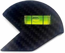
I typically use three methods to set tool height; the absence of a nub when facing, this gauge:' 1665684702649.png
or this dial indicator gauge, if I want to set a height other than the centerline: https://www.hobby-machinist.com/threads/making-tips-for-a-dial-indicator.67209/#post-561754 post#3
 
I tried your experiment on my lathe. I have a Grizzly piston type QCTP so not the best. I used a brazed tool for my reference surface. It had a measured 0º back rake and 1º side rake. For a repeatable z position, I set up my carriage stop. Once the tool holder was set, I could move the carriage multiple times to measure any influence due to movement of the carriage and I detected none.

I found that with a casual seating of the tool holder, I could see variations in tool height of up to .003". However, if I seated the tool holder, locked it, released it and relocked it, my total variation was .0006".

Normally, I tend to be fairly casual about changing tool holders so I would expect that my typical tool height variation is more like the former rather than the latter but good to know that of I am careful, I can be more precise in my repeatability.

I typically use three methods to set tool height; the absence of a nub when facing, this gauge:' View attachment 423260
or this dial indicator gauge, if I want to set a height other than the centerline: https://www.hobby-machinist.com/threads/making-tips-for-a-dial-indicator.67209/#post-561754 post#3

My toolpost is a Shars wedge type. I've taken it apart and cleaned/deburred the internals and put grease in it, otherwise it's as-sold by Shars.

Interesting results.
 
I have wondered about the relative merits of a piston versus wedge QCTP.

I suspect that it is mainly repeatability. A piston type could conceivably cock the tool holder slightly when locking which could lead to positioning variation in x, y, and height, The height variation I experienced with casual seating bore this out although the amount of variation bore was insignificant for the most part. (most tool height setting methods will have a height variation of multiple thousandths on a good day)

I haven't checked the variation in x and y but when I change tools, the first step os to re-reference anyway. If I bothered to create a tool offset table for my lathe tools, that would be a different story but that is not likely to happen unless I would have a CNC lathe.
 
Yes, agreed.

It makes me wonder.

Obviously my methodology was definitely NOT the most accurate possible. If we assume my results of plus .0005 ish to minus .0002, or therabouts, were pretty sloppy results, then the height repeatability is likely even better than my results indicate.
I could be mistaken, but I can't think of a scenario here where sloppy methodology could result in a false positive for repeatability, at least not 8 times in a row.


And, if a tool that's a much as .015" below center results in a part diameter to infeed variation of only .000085" (from the CAD sketch)

Then having a tool height variation of +/- half a thousandth would result in a pretty insignificant reduction of accuracy.

Indicating that for the most part, folks are vastly overestimating how much this matters when things like tool/part rigidity, tool sharpness, and lots of other variables have a more pronounced effect than height repeatability (within reason).
It's almost the same as checking the headstock to the bed. Any difference in centre height makes such a small difference. Remember; this is a lathe not a cylindrical grinder.
If a tool is 0.015 below centre does the error remain constant or does it vary? It seems to me that the theoretical triangle shape varies depending on the distance from the centre.
Nobody sets their tool within half a thousandth !! - it's a lathe.
 
Back
Top