Lathe leveling - do you do it with the lathe fully dressed or just the headstock and ways?

The Hardinge lathe three point mount comes to mind...
One pin, two ball in groove, all three spring clamped.

Sent from my SM-G892A using Tapatalk

Sounds like a semi-kinematic mount. Three balls in three v-grooves is one way. Or a ball in a cone, a ball in a v-groove, and a ball on a flat. A kinematic coupling has six points of contact (corresponding to six degrees of freedom). And there are a variety of ways of approximating that but getting more overall stiffness. They are especially important when you want to repeatably place something to the same location. And the idea is very much to prevent imparting moment loads on a structure.

As I understand it, the Harding mount is between the bed and the support casting? So if one wants to twist the bed there would be no way to do so? Only, I suppose rescraping/regrinding the ways.
 
The dual prongs of this discussion are amusing. One is “just try it you may need nothing” and the other is how to best achieve the ability to control bed twist. If your need to control bed twist is minimal, then your frame probably doesn’t need much in the way of modification. Yes, it will take a little longer to balance the adjustments while iterating toward the desired result, but overall time invested could be less (certainly money). In other words, you can achieve the same end point with very minor structural changes.
Yes, it is kind of weird. Can't say these kinds of discussions are unheard of on a machinist forum!

Attempted to take an RDM measurement with the bolts loose (finger tight on nut). Have a 20mm ground rod. Measured at 1" from chuck and 11" from chuck. Used an Interapid DTI. Was a little tough centering the vertical, as the QCTP moved when locking, but at least got close. (I'll have to deal with that later.) A measurement was made at 1" (centering the DTI in the correct plane) and then the carriage was moved to the new spot, 10 inches away.

In the H plane, I got a mean measurement of 8.65 at 1" and 6.65 at 11", measurements are in thousandths.
In the V plane, I got a mean measurement of 17.55 at 1" and 17.5 at 11", measurements are in thousandths.

So vertically, it is droop of the rod? (Like, don't worry about the vertical tilt.) Horizontally, the rod has an error of 0.002" over 10". This is all assuming that I did the measurement correctly. I clamped a Noga like indicator holder into an AXA QCTP holder. This was used to hold the DTI.

Raw measurements:
H @ 1". min: 8.3, max: 9.0, avg: 8.65
H @ 11". min: 3.3, max: 10.0, avg: 6.65
V @ 1". min: 17.5, max: 17.6, avg: 17.55
V @ 11". min: 17.4, max: 17.6, avg: 17.5
 
Like, don't worry about the vertical tilt.
Vertical misalignment of the carriage movement relative to the spindle axis is a cosine error, as that vertical movement doesn't change the cut radius all that much. So it's much less important than the horizontal misalignment.

0.002" change in radius suggests you would cut a 0.004" diametrical taper over that length. I'd be interested to see results from a two-collar test (turning two collars, 10" apart on a bar supported only in the chuck). I'd be inclined to try to address it, but maybe I should go measure my lathe before I spout off too much.
 
I went back to read your thread on mounting/leveling your G0602. Found it informative, but a bit hazy (for me anyways) to understand your implementation. At the end of the thread, if I recall correctly, is a link, but it is a circular reference, meaning it just goes back to the same thread.

Do you have any pictures, sketches or drawings of what you ended up with? Did you just add sub plates on top of the channel to do the adjustment? Were the sub-plates tied to the channel, or were they just supported by the 3 jack screws? Are the sub-plates larger than the lathe feet? If not, how did you access the jack screws?
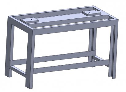
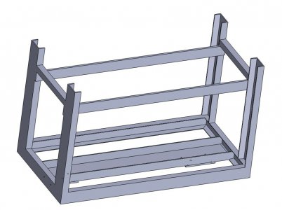
My concern was that the relatively thin web of the 7" channel would flex rather than the more rigid lathe bed. The flanges of the channel provide additional rigidity and the sub plates bridge the web by fastening closer to the flanges. It's not ideal but it is definitely an improvement on what I had. The proof of that was that previously, I would make shim adjustments but without effect whereas now the do.

Here is a graphic of my lathe stand. The sub plates are threaded and fastened through the table skin and chip tray to the channel.
Lathe 1.JPGLathe 2.JPG
 
Yes, the Hardinge mount is designed to -not- twist the lathe bed at all. Just hold it up. I might have mis-stated the bits... couldn't find a pic via my phone :-(

Sent from my SM-G892A using Tapatalk
 
My concern was that the relatively thin web of the 7" channel would flex rather than the more rigid lathe bed. The flanges of the channel provide additional rigidity and the sub plates bridge the web by fastening closer to the flanges. It's not ideal but it is definitely an improvement on what I had. The proof of that was that previously, I would make shim adjustments but without effect whereas now the do.

Here is a graphic of my lathe stand. The sub plates are threaded and fastened through the table skin and chip tray to the channel.
View attachment 385760View attachment 385761
Thanks for the graphic, that helps me visualize your setup very well.

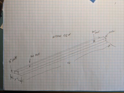
In my case, the outboard parts of the 1/4" plate are unsupported. The center section of the 1/4" plate is supported by the 2x2 welded along the length. Bottom view of mine is basically like:
PXL_20211117_195239563.jpg
Is there a (reasonable) way to modify or stiffen the unsupported area outboard of the 2x2 ?
 
Is there a (reasonable) way to modify or stiffen the unsupported area outboard of the 2x2 ?

If you put a piece of large channel over that, so the edges of the flanges are welded to the edges of the 1/4” plate, forming a box section with a tube in it, that would work. But then you’d need some structure for twisting the lathe feet relative to that stiff structure.

I think it’s a better approach to tie in to the frame and benefit from its stiffness (once skinned). For example, with longer cross bars that connect to the frame.
 
To stiffen the unsupported area one could use some MC6x12. I think this would be about the right size. It might even be possible to weld this in place around the tube. Of course, I'd need to remember to pre drill some holes for bolt access.

Still thinking about outriggers/tying into the frame. It seems easy, but it does put stresses on the frame that everyone thinks isn't very strong to begin with. Skinning or bracing seems reasonable enough.

I'm guessing that the two collar test will confirm the RDM, which tells me I will have a taper. Understood that the two collar is the only test that matters, but I don't understand what to do with the results. When I read about the two collar test, (from a link given by Richard King) it says the first thing you do is level the lathe - then you do the test. Color me confused. What does a two collar test do for me if the lathe isn't leveled, as compared to RDM and unleveled?
 
To stiffen the unsupported area one could use some MC6x12. I think this would be about the right size. It might even be possible to weld this in place around the tube.

That’s exactly what I had in mind. Also remember that for any of these stiffening approaches, you don’t need to weld the full seam. Just an inch or so every few inches will be plenty and will help minimize distortion.
 
Had a chance to deal with this again. Replaced the hockey puck feet with 1/2" thick, 4" diameter steel disks with a 140 degree dimple in them. Machined some screws with a matching 140 degree point. Did this on this lathe. Came out ok. With the solid feet it was easier to start to dial in the level. There was a strong correlation between screw angle change and markings on the level, yay! One good thing I noted was the levelness change as a function of carriage position is significantly less with the steel feet. However, I still saw 2 divisions of change from moving the carriage from the HS to TS. (0.02 mm / m) level.

Finding that adjusting the opposite end is strongly affecting the previous adjustment. By that I mean, I make the HS level. Then I go measure the TS and find it off. So I adjust it some. Go back to measure the HS and find it further off than the TS was. It doesn't seem to converge. Had to walk away from it, since the session wasn't going well. There seems to be an art to this, which I seem to be missing. Went back to leveling later, but it is more of the same, kind of like playing whack-a-mole at the carnival. Seems like there should be a better way to do this.
 
Back
Top