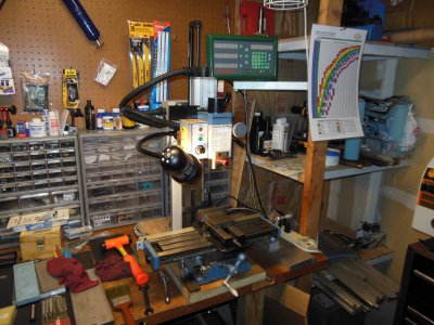
How do start my mini mill setup

To your original/latest question:

It's best to remove the saddle and table to drill and tap it. And it's not hard to do.

Remove the Y-axis handle and dial, being careful not to loose the little tension spring under the dial. I suggest covering it (dial) with a rag to keep it from shooting off to who-knows-where. :)

Then remove the support plate for the Y-axis screw by removing the two screws on either side of the screw.

Remove the leadscrew from it's brass nut by unscrewing it all the way out (towards you).

Loosen the gibbs screws on the right side of the saddle, and pull the saddle towards you/front of the machine so that you can see the nut under the saddle. Take a long allen wrench (I don't remember the size) and loosen the setscrew for the nut. It should just fall out onto the board you have under the mill.

Get a firm grip on the underside of the table, on either side of the saddle, and pull towards you. The gibbs will likely fall out, but that's OK, you can pick it up after you gently place the saddle/table somewhere where it won't fall and squish your foot.

Take the opportunity to check the ways, check the gibbs for flatness, even stone it maybe.

You have smaller scales that I, so you shouldn't have near the issues I had.

Reverse the process to re-assemble. Not that hard. :)

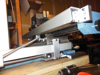
Here's a pic of my LMS and the back of the saddle. Kinda crowded, but I managed. Measure everything before you remove the saddle!

Bill
DSCN4138.JPG DSCN4137.JPG
 
Mill looks nice. Sounds like you are off toa good start. My first thought was to cover the electrical too. You will not believe how the chips fly.
Definitly a good idea to remove the table. That way you can better clean the packing grease. Make sure to lube every thing on the way back together.
If you do get stuck and you can not get with someone from the forum Chris at LSM will be able to help.
Enjoy the new machine and be safe.
Mark
PS we look forward to seeing your first cuts and projects and hearing more questions
 
Excellent. ill post when I'm done. It may be a couple weeks.

thanks again
 
3" precision vice

You will be much happier if you go with a 4-inch vise for this size mill... even a 5-inch is only moderately oversized, but will allow you to move it to a larger mill in the future.

These Kurt-style vises come with a swivel base, but the bases usually end up in the bottom of a drawer since you gain headroom with them off-- and nobody enjoys re-indicating the vise once it's moved.

Package deals appear nice, but sometimes it's better to spend a little more on the major items like a good vise with tee-nuts and bolts to secure it, and to buy the other accessories as you need them rather than compromise with what comes in the package. A good mill vise; a nice set of drills and a few center drills; an R8 collet set; and an assortment of end mills, will allow you to do a whole lot of work-- including making your own tee-nuts and hold-down clamps, etc.
 
Last edited:
Agree with the 3" vs. 4" vise statement. I bought a 3" and I'd have been much happier with a 4".

Unless you're working on small(er) stuff that fits well in a 3". In that case just ignore this. :)

Bill
 
Without trying to be nitpicking, most electrical codes call for 3 feet of clearance in front of those load centers.
Enjoy your new machine

I don't know if I've ever seen a panel where they left that kind of clearance. It's amazing what people will pile in front of them. Unless you have openings in the cover, chips aren't as likely to get inside.

Actually, a more common hazard will be a plug pulling a sixteenth or two out from the wall. A chip can fall behind it and give you a nice little arc when it touches the hot and neutral.

The best protection is a chip curtain around the back of the mill. It will keep chips out of the wiring and aid with cleanup.
 
I've already shifted some things around and moved the bench to a clear wall in the garage. I still need a chip guard for my bicycles that are hanging next to the bench in the new spot.
 
I also bought a model 3960 mini mill from LMS a little over a year ago & installed a power feed unit for the X axis, spindle tach unit, a gas counterbalance for the spindle drive & tooling & just finished installing a X & Y axis DRO from DRO Pros. Now I feel ready for some serious milling! Personally, I recommend all these mods; I first time I used the mill the part I was cutting ran into the original torsion spindle counterbalance. A belt drive for the spindle comes standard.

I didn't remove the table &/or saddle from the base but I did remove the column to lighten it so I could orient it easier to allow drilling the base & saddle for the DRO scales & read heads. I chose to mount the Y axis scale & read head differently from what the instruction booklet shows; my philosophy is to keep anything with wiring or hoses on it as stationary as possible. So, I mounted a piece of 1/8 X 1 1/4 X 1 1/4 in. steel angle to the saddle & the scale & alignment tooling was mounted to the angle. The Y axis read head mounts to the base below the saddle.

I trammed the column last spring but, since I removed it to simplify installing the DRO scales, I had to tram it again. Last spring I made up a simple mount for the indicator & had decent results [within 0.002 in.]. This time I wanted to get it nearly perfect so I studied the instructions in the manual &, to my surprise [at first] I overcorrected the error. The manual said to center the table under the spindle & take readings as far from the spindle as possible. I made an indicator mount that reached nearly to the 4 corners of the table & immediately found an error from the highest to the lowest corners of about 0.045 in. which seemed pretty high. I added 0.045 in. shims to the corner with the highest deviation from "0" & was surprised to find it even further off & in the opposite direction! After pondering this I came to the conclusion that increasing the distance between indication points to a distance that's greater than the column mounting bolt pattern magnified the error & adding this much shim thickness grossly overcorrects the problem. Bottom line: measure the spacing between the column mounting bolts & sweep the table [using parallels or smooth 1-2-3 blocks to avoid slots in the table] in a pattern the same size as the mounting bolt pattern. I then measured it this way, shimmed it again as indicated &, after I tightened the bolts, the runout was 0.0005 in. Checking it again from one corner of the table to the other I had about 0.002 in. Hope this is helpful.
 
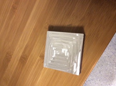
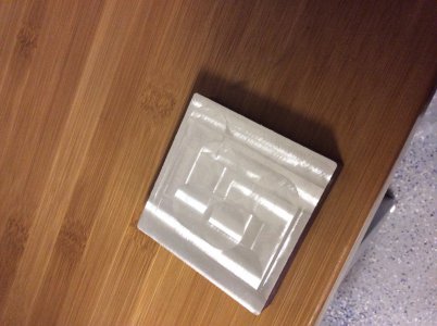
Ok everyone I made my first chips a little bit ago. I needed to make some 0.5" blocks for mounting my dro scales. I used the cutting speed calculator from little machine shop website. I was using a 3/4" two flute end mill with an RPM of about 840. I have an optical tach that counts the passes of a reflective tape on the spindle. I got a bit of understanding on the feel of how fast to turn the handles to keep from chattering and heating up. I machined two sides and ended up a little thinner than I would have liked with a thickness of .485. The first side was Fairly even but did not have a perfectly smooth surface. My second side gave me some trouble. It may have been how I was milling in a spiral around the piece. I found that as I was going around the end mill was cutting deeper than the last pass. Once I realized it was too late and I went passed my needed depth. I think the spiral process was lifting my piece from the vise since the parallels that the metal was sitting on we're loose. I then reset the piece on the parallels and quickly tried to even out the surface. I thought that the vise was really tight Any tell tale signs of what I'm doing here? I'm going to do two more blocks. Hopefully after I get some advice.

image.jpg image.jpg
 
Well I've not attempted an endmill that size, so can't speak to that. Did you tram the head/column?

When doing similar work, I normally just cut in the x-axis direction, normal not climb milling. I make sure the z-axis locks are TIGHT as I have seen head movement on my DRO if they are just 'snug'. I keep the cuts relatively small, as this is a small machine and doesn't have the mass/rigidity of the big machines for larger cuts. The harder the material, the smaller the cut.

When mounting the workpiece (on parallels or otherwise) I use the deadblow I keep right next to the mill to make sure the workpiece hasn't shifted as the vise was tightened. Easier to check on parallels as you can check to see if they are loose. when using my grooved jaws, I just smack it a couple of times for good measure. Seems to work for me. :)

Snug everything down, check you measurements twice, check 'em again, and give it another go. This is all part of the learning process. Have fun! :D

Bill
 
Back
Top