Horizontal Twin

Thanks Chris

Perhaps easier to not loose cam indexing, just unbolt the mounts from the head with the shaft in place.
Since the cams are individually adjustable it is easier for me to just pull the cam shaft out the side. If I remove the cam mounts then I would have to reset the valve clearance and alignment of the shaft. Not hard to do but finicky to get everything set back in place.

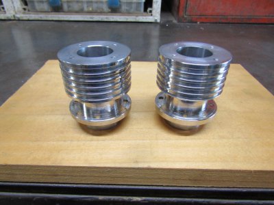
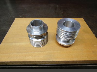
The 2" aluminum rod came in so on to the cylinders.
All roughed out.
IMG_2553.JPG

Holes drilled and tapped with a little shine.
IMG_2554.JPG

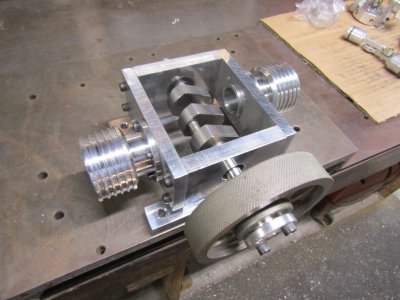
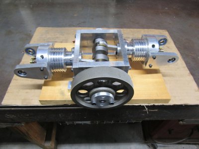
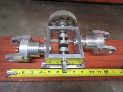
Cylinders bolted on the frame and the holes even lined up.
IMG_2557.JPG

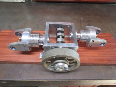
I am thinking of painting the flywheel black to give the engine some color contrast.

Anyone, your thoughts on painting and the color?

Thanks for looking
Ray
 
Awesome project. Very inspiring!
I wouldn't paint the whole flywheel. Just the inside part and leave outer rim part alone. My lathe has deep red ion the inside part on the hand wheels, which looks really nice.

Sent from my SM-A528B using Tapatalk
 
Just my opinion, but I like raw metal!
 
deep red ion the inside part
Thanks Gray that does sound nice and will set it off


Just my opinion, but I like raw metal!
Still open to suggestions but will probably leave it like it is for now.

I made a couple of head gaskets, lapped the valves and put the heads on.
I had a big smile on my face as I have good compression on both cylinders.

IMG_2561.JPG

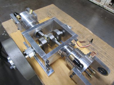
The engine is growing more than I expected.
IMG_2562.JPG

Thanks for looking
Ray
 
The engine will have two ignition modules, two hall sensors, and two magnets on a adjustable disk. I could have bought a module that has two high voltage outputs but the cost would have been some higher than using these two and since I had these modules that is what I will use.
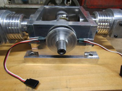
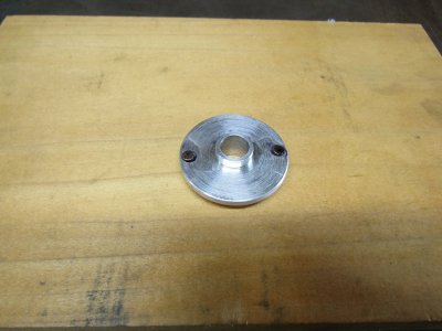
Magnet disk with magnets.
IMG_2564.JPG

And the other side.
IMG_2566.JPG

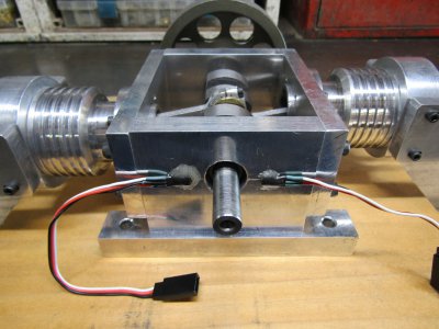
Two hall sensors mounted 180 degrees apart.
Epoxied in place.
IMG_2569.JPG

The disk installed and the engine timed and checked.
IMG_2570.JPG

Thanks for looking
Ray
 
I turned the heads over so the ports are on the top of the engine instead of the bottom as there just wasn't enough room on the bottom to make a nice job of it.
IMG_2574.JPG

I made four short brass nipples that screw into the intake and exhaust ports. On the intake nipples I soldered a copper 90 and another brass nipple.
IMG_2576.JPG

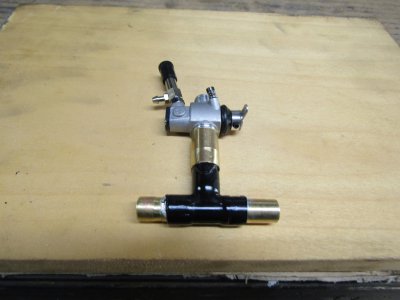
This shows the parts for the carb and manifold.
IMG_2578.JPG

Thanks for looking
Ray
 
That looks good but, I hate that you're blocking the view of the crank.
 
Back
Top