Horizontal Twin

Robert it's made of cast iron and I have several places where I store parts like this. The places should be labeled mistakes and I make a lot of them.:oops:

I have never started on the cylinder heads before I make the cylinders on any of my engines but I just had to do something while waiting on the 2" aluminum to get here.

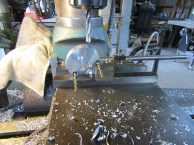
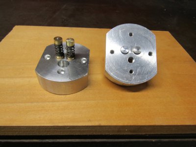
I spotted the holes for the head bolts, spark plug, and valve cages.
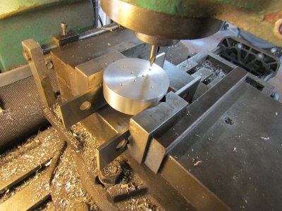
IMG_2507.JPG

On the drill press I drilled the rest of the way through the head and counter sunk for the head bolts..
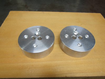
IMG_2509.JPG

Thanks for looking
Ray
 
All right I have made up my mind to make the twin with overhead cams. I have never tried this before and there are not a lot of home built examples to look at. The cylinder heads are 2.5" in diameter in order to give me some room for the cam brackets.


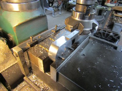
Here I am taking 0.250 off two sides of the cylinder head to give me a flat place to mount the cam brackets.
IMG_2512.JPG

The intake and exhaust valves are 0.110 offset lower from the center line of the head to allow room for the spark plug above them.
The intake and exhaust valve ports are both on an angle and exit on the lower side of the head.
This shows drilling those ports so they intersect with the valve guide holes.
IMG_2514.JPG

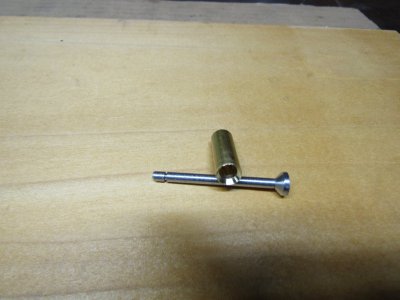
I made up 4 each of the valve guides and valves.
IMG_2522.JPG

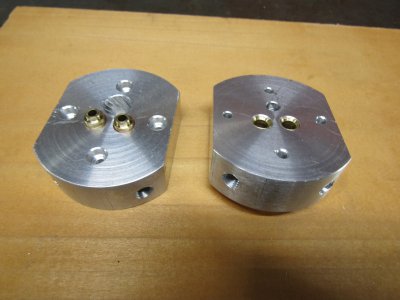
Here are the heads with the valve guides installed and the connecting ports drilled through the guides and the ports tapped 5/16 X24.
IMG_2518.JPG

This will be interesting.
Thanks for looking
Ray
 
Thank you savarin for the kind words.
This may not work but I have always wanted to give it a try.

Ray
 
I studied for some time as to how to get this to work and thought about a small bucket over the ends of the valve stems and keepers. They could be machined to different internal lengths to achieve the proper valve clearance but how to keep them in place. Every idea I came up with involved some sort of guide for the buckets and it would be a pain to work on.

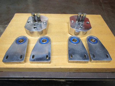
So I went a different course and threaded the valve stems to accept brass stubs that the cams would push on directly. Simple and easy but there is still the matter of side load on the valve stems. I'm going to give it a try.will give it a try.
The side supports will be adjustable to get the valve clearance.

IMG_2523.JPG

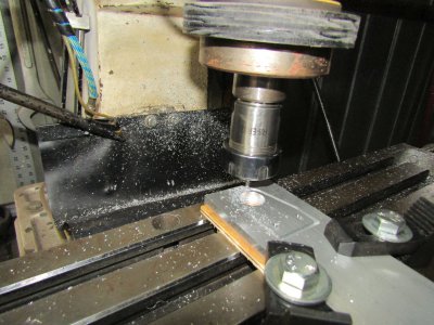
This shows one of the supports being cut on the CNC.
IMG_2527.JPG

Thanks for looking
Ray
 
I turned a couple of shafts for the cams to mount on and I left the ends long for now. They can be trimmed off later when I know where everything goes.
IMG_2540.JPG

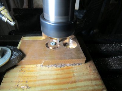
This shows cutting one of the cams from 0.400 thick bronze on the CNC.
IMG_2544.JPG

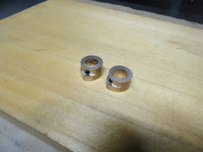
Two of them drilled and tapped with the set screws.
IMG_2546.JPG

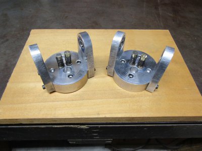
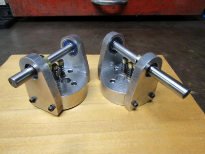
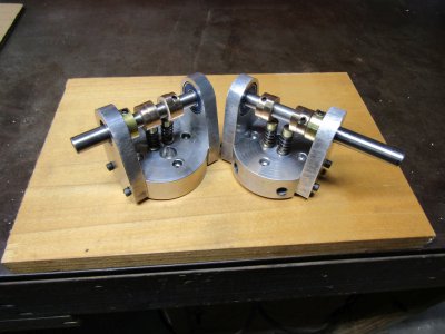
The heads are complete and ready to install.
IMG_2550.JPG

I was concerned that there may be excessive side load on the valve stems but that won't be a problem as they operate very smoothly.

The aluminum for the cylinders did come in so that is the next parts to make.

Thanks for looking
Ray
 
It looks like access to two of the head bolts is limited by the cam assembly? Would it be useful to rotate the bolt holes by 45Deg on the next one?
Looks superb by the way.
Edit: i see that would interfere with your ports. I guess its not a big deal to remove the cam assembly.
 
You're correct on both items Robert. The cam shaft can be removed by loosing three set screws one each on the cam lobes and the shaft retaining ring.
 
Perhaps easier to not loose cam indexing, just unbolt the mounts from the head with the shaft in place.
 
Back
Top