-
Welcome back Guest! Did you know you can mentor other members here at H-M? If not, please check out our Relaunch of Hobby Machinist Mentoring Program!
You are using an out of date browser. It may not display this or other websites correctly.
You should upgrade or use an alternative browser.
You should upgrade or use an alternative browser.
Help with Harbor Freight switch.
- Thread starter Qmavam
- Start date
- Joined
- Apr 30, 2015
- Messages
- 11,328
Questions:
1) Do you currently have 4 wires coming from motor? If so then you are fine. One pair should show very low resistance <5 ohms. (main windings)
2) Is one blue wire thicker than the other? Not too important but can be a helpful bit of info.
3) Did you remove all jumper wires from switch or are they still in place in their original positions?
-Mark
Last edited:
- Joined
- Apr 30, 2015
- Messages
- 11,328
Guess the first question should have been: Did you get the switch back together? You had said you had pictures of the original wiring so I wasn't sure
if you needed a diagram to hook everything back up. The switch should show continuity between terminals like the truth table in post # 11
Also I was in error in post #6- the new switch should match the old and have 16 terminals not 12
if you needed a diagram to hook everything back up. The switch should show continuity between terminals like the truth table in post # 11
Also I was in error in post #6- the new switch should match the old and have 16 terminals not 12
Last edited:
No, the switch is not back together. If I get it back together with all the cams in proper position,Guess the first question should have been: Did you get the switch back together?
I will not have any problem wiring it properly. I have pictures and diagrams, I'm confident that
I can put the switch back on the mill and wire it. I don't want to reassemble it until I know what position to put the cams in.
The problem is reassembly. Getting the cams right, I think I can do it, IF I know the route the current will have to take
through all four sections of the switch.

Questions:
1) Do you currently have 4 wires coming from motor? If so then you are fine. One pair should show very low resistance <5 ohms. (main windings)
2) Is one blue wire thicker than the other? Not too important but can be a helpful bit of info.
3) Did you remove all jumper wires from switch or are they still in place in their original positions?
-Mark
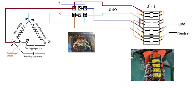
I'm sneaking up on a wiring diagram of AC in, switch with all contacts, and 4 wires from motor.
Please confirm or correct the two capacitor motor schematic matches the HF motor.
The drawing below has the two wires that measure 0.4Ω connected to the switch.
My thinking is that those two wires go to the Main motor winding.
Please confirm or correct that if I'm wrong.
I don't know where the other two wire go to on the two capacitor motor diagram.
Once I get this right, I can figure out what contact need to close for FWD and then REV.
Thanks, Mikek

- Joined
- Nov 25, 2015
- Messages
- 8,316
those switches are a bear. I had to take one apart to see what it was doing inside.. just curiosity. it was so hard to put back together.. I'll never do that again. They are great switches though. I used mine for a HVAC blower. It's my big blower to remove bad air, fire smell and soot (wife nearly set kitchen ablaze years ago), and spraying. It has a 4 speed motor, and is too powerful most of the time on low. So I use a smaller one now.Note to self, always take pictures, and then take better pictures.
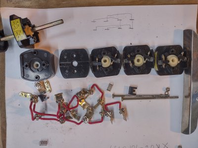
The FWD/OFF/REV switch on my HF 33686 Milling Machine stopped working most of the time, intermittently worked.
So I took it apart, I did find two sets of contacts that were burned and pitted, but were far from the worst I have seen.
I cleaned them up. Now that I have torn it all apart, I'm questioning whether the switch even had a problem, because after several
assemble and check of rotation, cams and switch pointer, all of the sudden I turned the switch and the shaft dd not turn. Then the screw
to tighten the clamp around the shaft becomes obvious.
This leads me to believe that the original problem was the knob rotating around the six sided shaft feeling like a detent, and not switch contacts.
I run the machine on 120Vac.
Now I'm trying to reassemble the 4 section switch with 12 springs and 16 separate contacts that need to be put into place.
And then the cams also need to be installed properly, however, I think they are all in the same orientation, so that may be easy.
AC---Hot and Neutral come in on two connections and on the opposite side are 4 connections that go to the motor.
I can probably do this* if someone can give me a drawing with 4 wires from a motor wired for 120Vac showing how
forward and reverse are implemented. Even if it uses 2-SPDT switches to show the wiring.
Can someone make or find a drawing of such.
**Assumes parts don't go flying more times than I can find them. Already lost a spring but the junk draw had one.
I've searced the carpet for a part 5 times already.
- Joined
- Apr 30, 2015
- Messages
- 11,328
Here's some options for you:
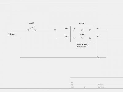
1) I see from the picture of the motor terminal block that you could use a simple on/off switch to run the machine until the new switch arrives.
I'll post a simple drawing for that- you would tie the browns together and the blues together and apply power to the pairs. For one direction.
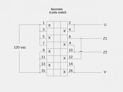
2) You should be able to use the truth table to reconstruct the cams- it's all there, but trying to do it with the jumper
wires in place makes the job much more difficult- Like a Rubik's Cube. Also, you would need to remove the jumpers anyway to test continuity- You are doing it the hard way. You would be better off to just do option #1 for now and wait for the new switch. Jumpers can be addressed then.
3) The motor isn't currently as the post #26 shows- the main windings are already on separate terminals (the pairs with straps) -
the single terminals with brown and blue are the start leg complete (winding + caps + switch)
Last edited:
- Joined
- Apr 30, 2015
- Messages
- 11,328
- Joined
- Apr 30, 2015
- Messages
- 11,328


