-
Welcome back Guest! Did you know you can mentor other members here at H-M? If not, please check out our Relaunch of Hobby Machinist Mentoring Program!
You are using an out of date browser. It may not display this or other websites correctly.
You should upgrade or use an alternative browser.
You should upgrade or use an alternative browser.
Harbor Freight milling machine drum switch wiring
- Thread starter bradybroussard
- Start date
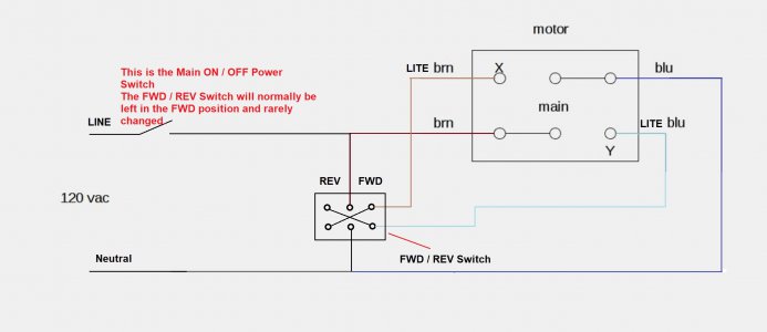
OK, I have the mill working with a DPDT ON / ON Switch
(https://www.amazon.com/Baomain-Toggle-position-mounting-terminal/dp/B01MSWTEB0)
and a SPST ON / OFF Power switch.
(simple 20A light switch) https://tinyurl.com/3ncav5bx
The DPDT ON / ON switch controls FWD / REV and is normally set to FWD position and left alone.
The SPST ON / OFF switch is the Main Power Switch and is used to turn the mill ON and OFF.
I have my mill wired like in the diagram below and works just fine. (120V)
Many thanks to markba633csi.
Mikek

IGNORE THE POST ABOVE, I think it is wrong. I'm still trying to solve how the Jumpers are connected. If anyone has, or will take a picture of the jumpers and will post it, I will give you my undying gratitude.I didn't note your post before my last post, so here is the way the RED jumpers are wired on the switch.
P.S. We still need the position of the Cams.
Do you know them?
View attachment 443354
I have this picture but I can't tell where some of the wires go.
Thank, Mikek
I'm looking for help to go through these diagrams of my proposed wiring of the 4 section switch.
Refer to post #22 which is a known working wiring, (although I think FWD and REV are backwards in the drawing)
I have labeled what is kind of a truth table, that is based on the diagram in post #22.
Thanks, Mikek
PS. it looks like the two cams are one way and the other two are turned 180*.
Refer to post #22 which is a known working wiring, (although I think FWD and REV are backwards in the drawing)
I have labeled what is kind of a truth table, that is based on the diagram in post #22.
Thanks, Mikek
PS. it looks like the two cams are one way and the other two are turned 180*.

Last edited:
SUCCESS!!
I got the switch put together with the cams in the correct positions, reinstalled the jumpers and put the switch back on the mill and it works as it should.
So, for those that may have to reassemble the switch, I'll pass on some info, the first assembly took 3 hours, I had something wrong and had to take it apart, but the second assembly was only 40 minutes because I learned so much on the first assembly.
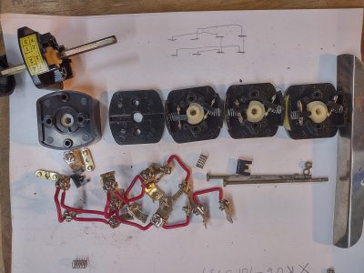
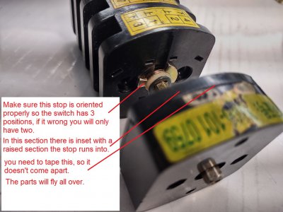
First make sure this stop is in the proper position.
Don't attempt to install contacts back into the switch with the wires attached, just take all the wires off.
Of the 16 contacts with screw terminals, there are two styles, make sure you note that and insert them properly. All screws point the same direction.
The short movable contact must also be installed correctly, don't flip it. When it's assembled properly the actual contact dots will be able to make connection.
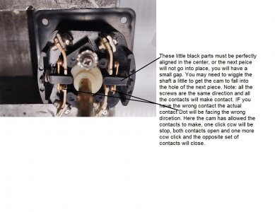
After sliding on the first black section, install the cam first. To orient it properly, you will need to Identify the FWD position, the cam should allow the bottom contact to close. You will probably have to put all the parts in to identify how to orient the cam. In STOP both contacts are open, In FWD the bottom contact will close, in REV, the top contact will close. You will have to hold all the parts together when you move from stop to FWD and REV use two fingers across them, one on each side of the shaft. Hold down the little black part with the spring behind it.
Be sure as you add a section you cut some masking tape and tape the assembled parts together, you don't want it o fall apart.
I just said to tape the parts together, don't ignore that!
Continue the assembly until you have installed the rear cover and installed the two long screws and nuts.
Then you need to check continuity in FWD and REV.
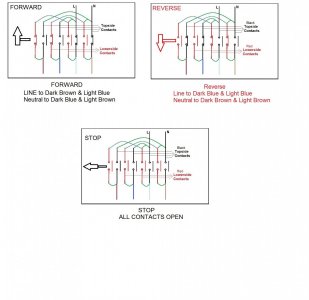
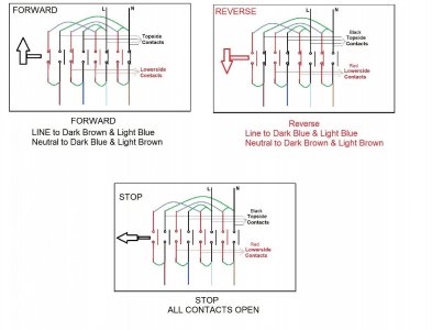
You can use this diagram to figure out the contacts should read closed, in FWD and REV,
Note the contacts in RED are the lower contacts, in FWD the first two lower contacts should read zero and the last two upper should red zero.
In REV the first upper two should read zero and the last two lower two should read zero.
If you have this correct, now you can install the jumpers.
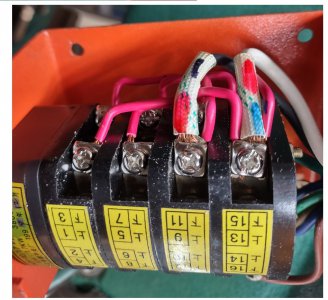
Here's a picture show how the jumpers are placed.
Note: when the switch is mounted on the machine these wire are towards the floor.
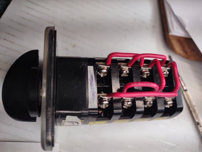
An d here is the side towards the ceiling.
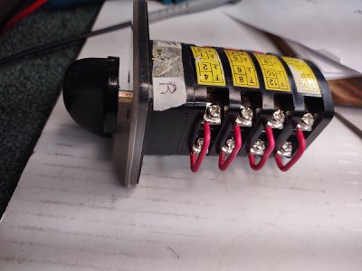
You can use your ohm meter to verify that it is correct.
This diagram should help.
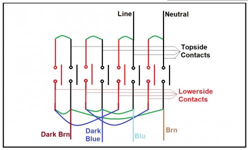
All that's left is to install the switch and connect the six wires.
The diagram above will guide you to put the Blue and brown wire in their proper place.
If you have different color wires, you can open the box on the back and see what color is connected where the links are connected.
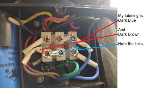
I'll be happy to help if I can.
Mikek
I got the switch put together with the cams in the correct positions, reinstalled the jumpers and put the switch back on the mill and it works as it should.
So, for those that may have to reassemble the switch, I'll pass on some info, the first assembly took 3 hours, I had something wrong and had to take it apart, but the second assembly was only 40 minutes because I learned so much on the first assembly.
First make sure this stop is in the proper position.

Don't attempt to install contacts back into the switch with the wires attached, just take all the wires off.
Of the 16 contacts with screw terminals, there are two styles, make sure you note that and insert them properly. All screws point the same direction.
The short movable contact must also be installed correctly, don't flip it. When it's assembled properly the actual contact dots will be able to make connection.
After sliding on the first black section, install the cam first. To orient it properly, you will need to Identify the FWD position, the cam should allow the bottom contact to close. You will probably have to put all the parts in to identify how to orient the cam. In STOP both contacts are open, In FWD the bottom contact will close, in REV, the top contact will close. You will have to hold all the parts together when you move from stop to FWD and REV use two fingers across them, one on each side of the shaft. Hold down the little black part with the spring behind it.

Be sure as you add a section you cut some masking tape and tape the assembled parts together, you don't want it o fall apart.
I just said to tape the parts together, don't ignore that!
Continue the assembly until you have installed the rear cover and installed the two long screws and nuts.
Then you need to check continuity in FWD and REV.
You can use this diagram to figure out the contacts should read closed, in FWD and REV,
Note the contacts in RED are the lower contacts, in FWD the first two lower contacts should read zero and the last two upper should red zero.
In REV the first upper two should read zero and the last two lower two should read zero.

If you have this correct, now you can install the jumpers.
Here's a picture show how the jumpers are placed.
Note: when the switch is mounted on the machine these wire are towards the floor.

An d here is the side towards the ceiling.

You can use your ohm meter to verify that it is correct.
This diagram should help.

All that's left is to install the switch and connect the six wires.
The diagram above will guide you to put the Blue and brown wire in their proper place.
If you have different color wires, you can open the box on the back and see what color is connected where the links are connected.

I'll be happy to help if I can.
Mikek
SUCCESS!!
I got the switch put together with the cams in the correct positions, reinstalled the jumpers and put the switch back on the mill and it works as it should.
So, for those that may have to reassemble the switch, I'll pass on some info, the first assembly took 3 hours, I had something wrong and had to take it apart, but the second assembly was only 40 minutes because I learned so much on the first assembly.
First make sure this stop is in the proper position.
View attachment 443670
Don't attempt to install contacts back into the switch with the wires attached, just take all the wires off.
Of the 16 contacts with screw terminals, there are two styles, make sure you note that and insert them properly. All screws point the same direction.
The short movable contact must also be installed correctly, don't flip it. When it's assembled properly the actual contact dots will be able to make connection.
After sliding on the first black section, install the cam first. To orient it properly, you will need to Identify the FWD position, the cam should allow the bottom contact to close. You will probably have to put all the parts in to identify how to orient the cam. In STOP both contacts are open, In FWD the bottom contact will close, in REV, the top contact will close. You will have to hold all the parts together when you move from stop to FWD and REV use two fingers across them, one on each side of the shaft. Hold down the little black part with the spring behind it.
View attachment 443675
Be sure as you add a section you cut some masking tape and tape the assembled parts together, you don't want it o fall apart.
I just said to tape the parts together, don't ignore that!
Continue the assembly until you have installed the rear cover and installed the two long screws and nuts.
Then you need to check continuity in FWD and REV.
You can use this diagram to figure out the contacts should read closed, in FWD and REV,
Note the contacts in RED are the lower contacts, in FWD the first two lower contacts should read zero and the last two upper should red zero.
In REV the first upper two should read zero and the last two lower two should read zero.
View attachment 443682
If you have this correct, now you can install the jumpers.
Here's a picture show how the jumpers are placed.
Note: when the switch is mounted on the machine these wire are towards the floor.
View attachment 443684
An d here is the side towards the ceiling.
View attachment 443685
You can use your ohm meter to verify that it is correct.
This diagram should help.
View attachment 443686
All that's left is to install the switch and connect the six wires.
The diagram above will guide you to put the Blue and brown wire in their proper place.
If you have different color wires, you can open the box on the back and see what color is connected where the links are connected.
View attachment 443688
I'll be happy to help if I can.
Mikek
Just wanted to add, after you install the first two cams correctly, the other two are 180* the other direction.
It will all become clear as you ohm it out.
Also, I could not have done this repair without the info markba633csi gave me on the alternate wiring using two switches.
Thanks very much markba633csi.
Edit to add the model number hoping if others search they will find the post.
Harbor Freight #33686 milling Machine.
Mikek
Last edited:
- Joined
- Feb 4, 2021
- Messages
- 12
Wow! I've been gone too long . Walked by my mill today and decided it was time to finally figure this out. Qmavam looks like you put some work in !
I hope I posted enough info for you to put yours back together. That was my intention. My mill works perfectly since the switch was put back together. Ya, I did put a lot of work into it, I kinda took a long route, but once I got the info in post #22, I then figured out how to rewire the original switch.
If you just want to take the easy route, wire it as in post #22.
Mikek
If you just want to take the easy route, wire it as in post #22.
Mikek


