Harbor Freight milling machine drum switch wiring

Found this one on Amazon
e9f8c0e979c7802343fcccbe7959c146.jpg
a9143d4dd2ea45bdb93d9efbb4a58ee5.jpg
9c1f73e87ca3fa87ee6352f55e46623d.jpg


Sent from my SM-N950U using Tapatalk
 
Did it come with a diagram? (truth table) Or is there a diagram on the page where you ordered it?
-M
 
No diagram. This is just a 16 pole 3 position drum switch. You can do all kinds of stuff with it. I just want to run. My mill.

Sent from my SM-N950U using Tapatalk
 
You'll need to "ring it out" with a ohmmeter to see how the contacts connect internally, because unfortunately these switches come in different versions. You do two sets of tests: one in forward and another in reverse, and you write down what connects to what, in each case. Once we know that I can do a sketch for you. Otherwise it's just guess work and that's a bad idea when dealing with electricity.
You can also use a battery and a small light bulb as a tester if you don't happen to have a meter handy.
-M
 
OK I see, switch is probably a lost cause. I can suggest some switches from Amazon and show how to wire it. I would plan on running this machine on 220/240 volts, because of the current draw
-Mark
OR if you want to just get it running quickly in one direction with a simple toggle switch we could do that instead. Reverse is less useful on a mill than a lathe
Mark
I have the same mill and my switch just went south. i would be interested in your input on wiring into a single switch? Never has used reverse and dont expect to. My assumption is to only wire one side but would prefer some expert advise to avoid a motor replacement. Any help is appreciated.
 
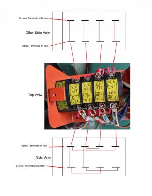
Yep. I've seen it before. Not very clear how the red jumpers are wired.

Sent from my SM-N950U using Tapatalk
Maybe not clear in my presentation, but I have Pictures and a drawing, very confident I can get that part right.
 
I had the same issue a couple of months ago with the added benefit of switching it to 220v and markba633ca got me sorted out.

The information from Mark that got me up and running is about 4 posts down from this one.

Joat
 
Yep. I've seen it before. Not very clear how the red jumpers are wired.

Sent from my SM-N950U using Tapatalk
brady, I have the red jumper positions drawn, the problem is, what position do the 4 cams go in.
I'll share how the jumpers go if you want it.
Mikek

P.S. After all this disassembly, I'm pretty sure the switch was fine. What happen is the knob detented around the hexagonal shaft. It felt like it was normal, but the shaft was not turning. After the fact, I recalled that the switch went around and wasn't limited to FWD/STOP/REV.
The Caution, "TIGHTEN SCREW ON THE KNOB, BEFORE ANY THOUGHT OF DISASSEMBLING THE SWITCH"
 
Last edited:
I have a mill and the switch is in pieces with wires removed. Can anyone with this mill send me a pic of the switch and where the wires are connected? Also detail on the jumper wire positions. To clarify... 16 poles on the switch. Forward off reverse. 2 capacitor motor. Thanks!

Sent from my SM-N950U using Tapatalk
I didn't note your post before my last post, so here is the way the RED jumpers are wired on the switch.

P.S. We still need the position of the Cams.
Do you know them?

Milling Machine wiring for brady.jpg
 
Mark
I have the same mill and my switch just went south. i would be interested in your input on wiring into a single switch? Never has used reverse and dont expect to. My assumption is to only wire one side but would prefer some expert advise to avoid a motor replacement. Any help is appreciated.
First thing to check, does your switch have more that the original 3 positions FWD/OFF/REV?
If it does, tighten the screw on the knob. My knob was rotating on the hexagonal shaft, it felt like detents, but it was just
a loose hexagonal hole rotating on a hexagonal shaft.
Mikek
 
Last edited:
Back
Top