Gene Weber's PM-728VT CNC Conversion

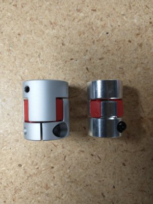
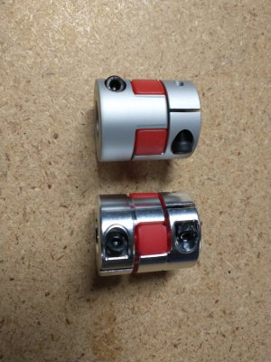
As noted in Koenbro's conversion thread, one side of the spider couplings are not the correct sizes for the Teknic servos. The Teknic servo shafts are 3/8" and 1/2". I found some inexpensive couplings ($9.99 & $13.99) of the correct size. Purchase information will be in the final parts spreadsheet.
IMG_20221230_165215390.jpgIMG_20221230_170004135.jpg
The shiny aluminum are the purchased replacements. The coupling for the NEMA 34 servo has the same dimensions as the PM supplied coupling, The coupling for the NEMA 23 servos is smaller diameter, but the same length as the supplied coupling. Very good quality parts.
 
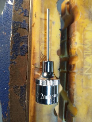
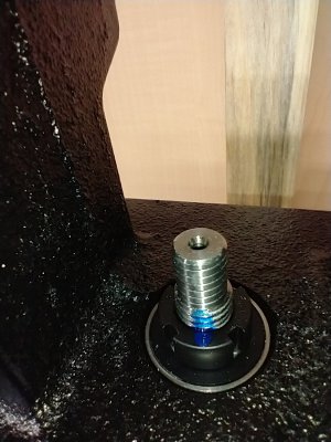
Assembly of the Z-axis was straight forward. I decide to torque the bearing locknuts to 50 in-lbs. That loads the bearings with 2126 Newtons of force. The ball screw moves well with no play. I bought a 2mm Allen socket from Napa to try and torque the locknut set screws to 31 in-lbs. Waste of money. The key is too long to apply that torque. I used a regular Allen key and pulled them as tight as I could.
IMG_20221230_180207865.jpg
The set screws are probably plenty tight, but I put a dab of nail polish on the bearing locknuts and threads. If they spin I'll be able to see it.
IMG_20221230_173218501.jpg
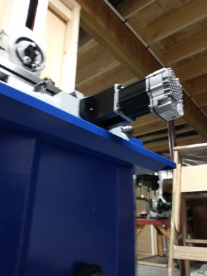
The NEMA 34 servo is attached with M6 cap screws. Unfortunately the holes in the Teknic servo, which are 7/32" diameter, must be drilled out a 64th to 15/64". I wasn't happy about making any mode to a $370 servo, but it had to be done.
IMG_20221231_132131405.jpg
I'm not experienced with buying this type of equipment. The ways were dirty, which may be common, so I wiped them down and gave them a thin coat of way oil before assembly. I also cleaned the grease off the head mount. I'm going to put some white lithium grease on that before mounting the head unit.
 
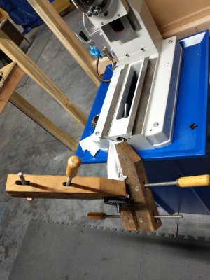
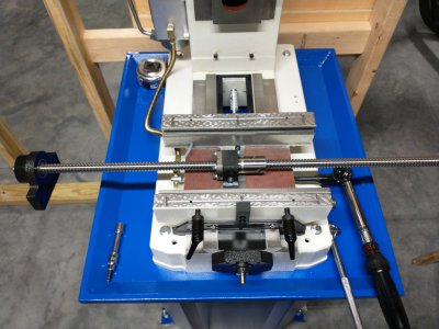
Watch the assembly order when you do the X-axis. First, you have to put the ballscrew through the casting and then put on the bearing assembly. Z and Y ballscrews I held in plastic jaws in my vice to torque the locknut. For the X-axis I managed to hold it with two wood clamps.
IMG_20221231_130336853.jpg
Don't forget to put the black sliding cover plates down before the bolting the X-axis sled to the ballscrew. I did.
IMG_20221231_133245738.jpg
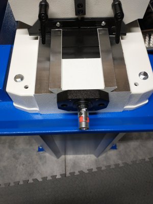
The spider coupling needs to be attached to ballscrew shaft and tightened before bolting on the servo assembly. There is not enough access to the coupling setscrew to tighten it after the servo assembly is in place. The chip tray blocks it.
IMG_20230101_091245523.jpgIMG_20221231_172135883.jpg
 
Last edited:
No gotchas with the Y-axis. Very straight forward to assemble.
IMG_20221231_154858198.jpg
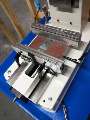
There is some slop in the ballnut attachment to the X-axis sled. I pushed it all the way back towards the "tower", and then made sure the ballscrew shaft was perpendicular to the side of the X-axis sled with a square. I made a pencil mark at the back of the mounting block. Then the block was slid all the way front, squared, and another pencil mark made. Then I centered the ballnut mounting block between the two pencil lines, squared it up, and torqued it in place.
IMG_20221231_154845301.jpg
IMG_20221231_162017767.jpg
 
Last edited:
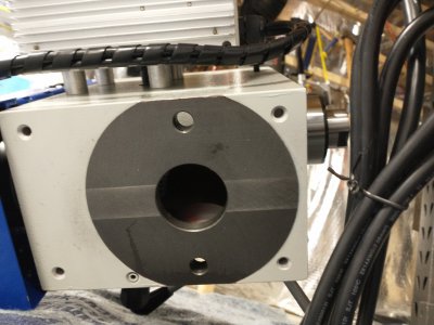
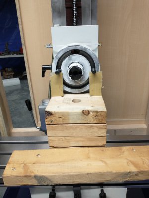
By taking a measurement on the back of the head unit, one can setup the position of the Z-axis sled and some 2x6 scrap to make re-installation of the head unit pretty easy. Basically have the top of the lumber ~1/4" below the circle.
IMG_20230101_093531601.jpg
I put white lithium grease on the gear teeth, and a light coating on the mounting surfaces. The bolts were temporarily held in place with two 3" long pieces of cardboard.
IMG_20230101_094958462.jpg
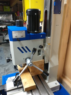
The head went on very easily. It will of course have to be trammed, but it's pretty much back at the original factory location. I don't even own an indicator and Christmas is whole year away. ;)
IMG_20230101_095538798.jpg
 
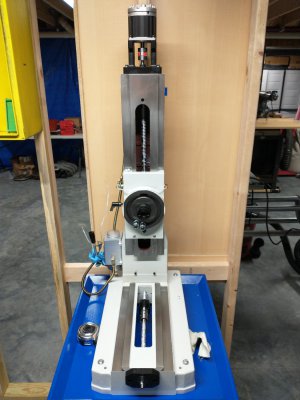
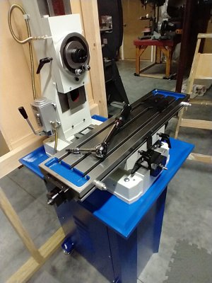
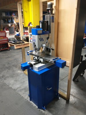
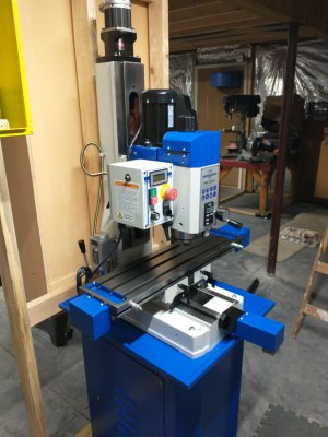
And here it is, the mechanical part of the CNC conversion done!
IMG_20230101_095923172.jpgIMG_20230101_095933548.jpg
A few notes / comments:

All of the cap screws were grade 12.9, and seemed of good quality. The following torques were used:
M8 - 31 ft-lbs
M6 - 149 in-lbs
M5 - 88 in-lbs
M4 - 43 in-lbs
M3 - 19 in-lbs
Bearing locknuts - 50 in-lbs
Setscrews used 2mm and 2.5mm Allen keys, and were just pulled really tight.

The lock washers are garbage. Two deformed when the screws were torqued. When some bolts were loosened to adjust things, and the lock washers didn't spring back. I think this is just the way it is today. I don't even know where one buys quality lock washers anymore.

There is no clearance for the cap screws against the sides of the Teknic servos, and you'll be hard pressed not to chew up the aluminum case of the servo just a bit. Minor, but those servos are expensive and beautiful, so it's a bummer.

The ballscrew kit contained 3 grease nipples I didn't use. There are setscrews in the ballnuts that I believe one would remove and replace with the grease nipples. I'm going to use dry Teflon spray lubricant on the ballscrew shafts instead.

The white paint on the Mill itself looks like a tough powder coat, but it chips very easily. It keeps flaking off around holes and machined edges. Not a big deal, but irritating.

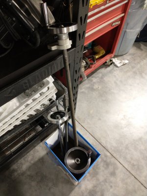
And, I have these cool removed parts to put into my pack-rat inventory. I'm sure I'll find a good project use for them!
IMG_20230101_180919249.jpg
 
I did a quick power supply hookup and used the Teknic ClearPath motor setup program to test the 3 axis. Everything works as can be seen these videos.

You may notice that the machine vibrates a bit when the X-axis is moving. When I mounted the X-axis sled I noticed that it was very hard to move compared to the Y and Z sleds. I'm wondering if I need to loosen that Gib slightly?

So now it's time to start filling the ugly yellow box with electrical components and electronics. I'll keep posting as I make progress on that.
IMG_20230101_180528222.jpg
 
Thanks for the heads-up Chris. Yes, I'm not sure what sort of tool could reach those 2mm setscrews, and also be strong enough to put 31 in-lbs of torque on them. I'm going to add the jam nuts with some loctite.
 
I forgot to mention that while the bearings fit easily into the Z-axis and X-axis blocks, they require some encouragement when put into the Y-axis block. I put a block of scrap wood on top of the bearing and lightly tapped it in with hammer making sure it was properly aligned between taps.
 
Back
Top