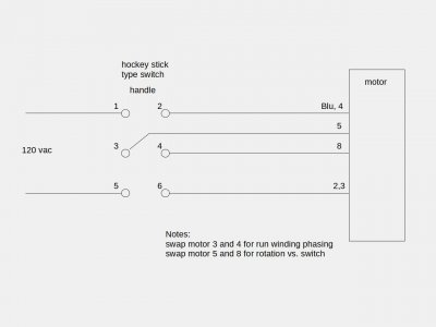
Drum switch wiring 120 volt

It was wired when I picked up the lathe, in the same configuration as it is in now, as I haven't touched it since testing it.
2, 4, and 5 wired together, 3 and 8 to hot, and the blue wire to neutral.
 
And it seems to run ok like that? That's weird, doesn't match the dataplate
Do you see a P2 wire?

I gotta run out but I'll look at it again later
 
No P2 wire. and, yes, it does run.

I tried to pull off the wiring box, and it didn't seem to have been removed at any point, so I can't see a wire tucked away or anything like that.
 
Well heck. That makes no sense. I guess I'll take a stab at modifying the sketch- but first-
Try this test to see if we can reverse it:
Connect 2,4, 8 together (wirenut) and 3,5 together to hot (blue to neutral as before) and see if it runs in reverse.
If so, then the connection below should work (although it doesn't make any sense to me)
You must be living over a meteorite since both your drum switch and your motor are weirded out- LOL
Edit: remove sketch temporarily while we discuss motor config
 
Last edited:
I found the time to go pull continuity checks on the motor, and blue and 2, 3 and 4, and 5 and 8 all make working pairs. So, two run windings and a start winding.
 
Ok then if that is true, your test setup is only using one of the run windings (I think)
Let me cogitate on that for a bit - I shall return- something still not adding up
So to recap:
Run A= blue and 2
Run B= 3 and 4
Start leg = 5 and 8
So no continuity between blue and 3 for example? Did you try the reversing test? (previous post)
 
Last edited:
So I drew it out and it looks like this (below): I would say it was wired for 220/240 by the previous owner
It may seem to run ok on 120 volts but it may not be. I'm guessing it's staying in start mode and not getting up to
the proper speed to kick out the start circuit; not developing full power
For 120 volts then we would expect Blu, 4, and 5 tied together and 2, 3, and 8 tied together- all elements in parallel
HOWEVER- something tells me that isn't correct either, since it doesn't match the dataplate (no P2 wire) and the polarity
of the two run windings is in question. The Blu wire may be the leg with the thermal button in series.
It would be wise to do a pair of run tests, one run winding at a time
to verify the polarity:
Test 1: Disconnect 2. Move neutral to 4 and 5; connect hot to 3 and 8. Apply power; note rotation.
Test 2: Disconnect 3 and 4. Connect neutral to Blue and 5. Connect hot to 2 and 8. Apply power and note rotation.
Should have same rotation direction in both cases
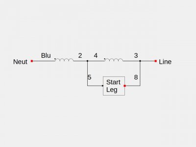
Leland1az.jpeg
 
Last edited:
I haven't had a chance to try the reversing test, but considering that all three windings show continuity I am confident of the wiring now. I also double checked and Blue only has continuity with 2. I am not sure why the motor has a plate showing 7 leads, as I didn't buy this new, but I am confident of the motors utility now.

When I check for it running, I only check so much as to see if it turned under power, and not to see how well it spun up. I think you are right, but I was thrown by the plug, as that is a standard 120 plug. Simple enough to wire it correctly, and go from there.

I do wonder if a bad data plate was put on, but the reality of it is that the plate is no substitute for the actual wires and real world tests. I could put a meg-ohm tester on it, but not sure if I need to go that far with it.

I should have it wired up to the switch tonight, and will let you know how it goes! Thanks for all the help.
 
No problemo- let me know
It's possible the factory made a design change and didn't update the dataplate
Hopefully this will do it:
Leland120v1z2.jpeg
 
Last edited:
A gap in my knowledge, but since this is AC, why worry about the phasing of the run windings? As long as all three are flowing in the same direction, which should happen as directed by the start winding, why would I need to switch the motor phasing by switching 3 and 4?
 
Back
Top