In section BB, you have over-defined the horizontal measurements. You should not have the overall dimension and the three dimensions adding up to that overall (1.250 and .250+.920+.080). as a machinist would not know which dimensions match your design intent. I would guess that the .920 dimension would be the one to leave off the print but that may be a critical dimension for you. From your block tolerance of +/- .003", if all the dimensions stacked unfavorably, the .920 dimension could be as small as .9111 or as large as .929.
That said, I often over-dimension on drawings for my own use because 1. it is convenient for me when I am in the shop not having to do the math to check a measurement and 2. because I know what the design intent is and which dimensions are critical. I have used parentheses around a dimension to indicate for reference only for drawings sent out to a job shop.
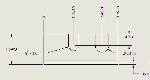
Another way to dimension horizontal and vertical positions is to establish a reference point and dimension using horizontal and vertical ordinates. The advantage of this is twofold. 1. There is no tolerance stack up as there would be when chain dimensioning. I use it when I have an array of features because a +/- .003" tolerance means that the feature is located within that tolerance at the nominal position. and 2. When actually machining, I will pick a reference point on my workpiece and all my machining positions are measured from that point.
For the hole positions, I would dimension each hole position from the center. Another way would be to draw a bolt circle and dimension the diameter. It wouldn't hurt to extend your center lines and add center lines for each of the holes. This will reinforce the location of the hole centers on the horizontal and vertical axes.
I usually do not put surface finish on a drawing unless it is critical. I have found that every machinist has a different idea of what a good part looks like and no two machinists will make the part the same. To that extent there is a component of artistry involved in machining. When sending work out, you quickly learn which machinsts do good work and which do not. Putting a surface finish on a drawing technically requires the machinist to verify the finish which adds extra cost. We did however, have some information in our title block
I generally don't use GD&T but it does come in handy when specifying things like perpendicularity, cylindricity, parallelness, etc. that would be hard to describe otherwise.
The important thing is to define your part in an unambiguous way. If you are machining the part yourself, it becomes very obvious if you have underdefined or overdefined. If you doing this in a work environment, you probably have a set of drafting standards to guide you.
Bob


 I can measure your part and tell you where you put the features, but does it match your design intent? No reference to features, just imaginary points in space. What should the diameter or depth of the groove to be, for example? I would dimension the edge of the groove from a known end of the part and then dimension the width. Then I would dimension from the OD to the ID of the groove. Sorry to be critical....too many years of inspection experience!
