Do These Prints Make Sense?

Dan_S

Active User
Registered
Joined
Aug 26, 2013
Messages
1,061
I'm just a hobbyist, but i've been messing about in cad for almost 15 years now. When I build stuff, I always make plans, but never anything with great detail, because since i designed the part I already know how to make it. I've recently started playing with Fusion 360, and it makes it a lot easier to generate prints from a 3d model than the software I've used in the past, so I've been trying to up my game by making more professional style prints.

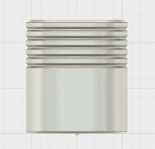
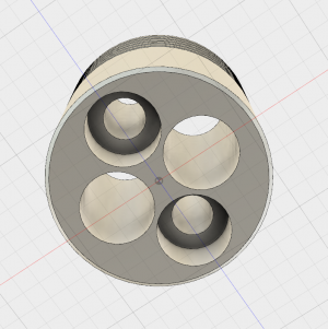
So if you made it this my far, my question is: If you were given the attached prints, could you build the part pictured below, without needing to actually see the part?

Basically am i good enough at making blueprints that I could give them to someone else.
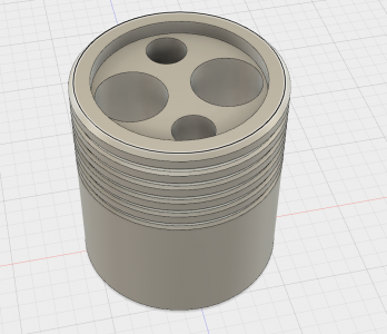
1.png

2.png

3.png
 

Attachments

  • sheet-1.pdf
    63.3 KB · Views: 106
  • sheet-2.pdf
    65 KB · Views: 66
I could build it. Looks like all of the needed dimensions are there, but it looks like the material call out is missing. Took me a second to figure out where the counterbores are, maybe add a hidden line circle to the top view to show the counterbore on the bottom on sheet 1. It's obvious in the 3-d views.
 
I understand them. Whether I could machine them is a whole different question!

But they are clear enough, assuming all dimensions are there.
 
Well if it had dimensions I could make it.


edit ] ok I didn't open the pdf. Looks good to me.
 
They look pretty good to me, an amateur. You even understand and list tolerances! Missing, however, is the material they are made of, and if applicable, surface finishes. Might be worth listing quantity needed as well.
 
It appears to me that you have not actually located the holes. I can infer where the centers are but it's best to be explicit. Have you studied geometric dimensioning and tolerencing?
 
Looks like all of the needed dimensions are there, but it looks like the material call out is missing.
Would that be something i just listed in the Title section? "Material: 6061-t6" or something like that?

Took me a second to figure out where the counterbores are, maybe add a hidden line circle to the top view to show the counterbore on the bottom on sheet 1.
Will do!

Missing, however, is the material they are made of, and if applicable, surface finishes.
How do you list surface finish? Do you call out an Ra number, is there some other standard for that?


It appears to me that you have not actually located the holes. I can infer where the centers are but it's best to be explicit. Have you studied geometric dimensioning and tolerencing?
To locate The holes, would i just give a linear dimension from the center of the part, to the center of the hole?

I haven't done any official studying. I can remember some stuff my dad taught me as a kid when I would watch him, review bluprints from work he brought home. Everything else I've learned from the fusion 360 documentation, and tidbits i could gleam form my copy of Machinery's Handbook. I've tried to review some ASME documents I've found online, but every time I start, my eyes start glazing over.
 
You guys need to read ALL of the prints;) See Sheet 1 & 2 PDFs


I noticed that the attachments where PDF's right after I posted. A lot of times I will see pictures in a post with an attachment of the same pic at the bottom. So I didn't pay attention at first. Sorry.
 
This is similar to what I usually get . doesn't always be in this order though.
upload_2015-12-18_22-56-33.png
 
Back
Top