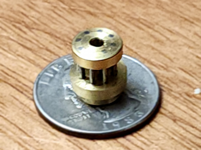
Debugging my lantern pinion

Hey now, hey now, hey now, WAIT JUST A MINUTE! I said the tram was good, I was really sure the tram was good.

I use one of those Edge Technology deals with two indicators. I know you can make one, and there are other methods, and I fell for a scam product that costs more than it's worth. Heard it all before. At the end of the day, though, you can't say it doesn't give accurate readings. Here is the setup, don't bother looking at the indicators.
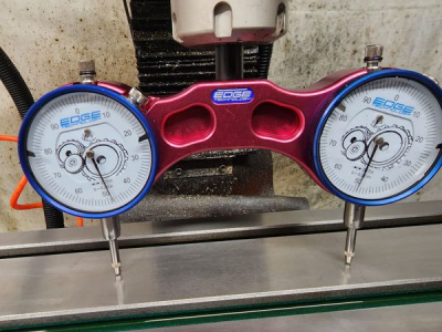
1662616878855.png

So after removing the fixtures and stoning the table. Oh yeah, I got it level too. Close enough.
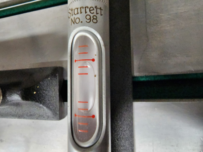
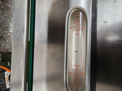
1662617019141.png1662617190283.png

I set the right gauge to 0 with the quill fine feed, and then I locked the quill. Both needles moved. It happens. It's a Chinese mill. Locking the quill always changes the depth by at least 0.001" and I just account for that. So with those caveats, these were the needles:
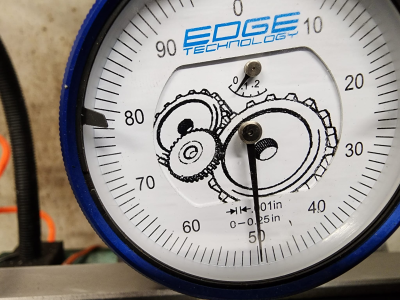
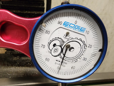
1662617337258.png1662617418681.png

So I guess somebody owes me $5.00 after all. I said it was in tram, and that is as good as the tram is ever going to get on a Grizzly g0704. I stand by this reading.

I'm very glad I don't have to touch the tram adjustment.

So how about the shims on the column?

It would have been great if these had read the same, but 0.005" of forward nod is not enough for me to mess with the shims. This adjustment is hard to make, and I chased the best reading obsessively. I know the calibrated shim stock I used didn't squish. The only adjustment possible is to loosen the four hex head cap screws holding the column to the base, apply shims, and tighten to full torque. At anything less than full torque, you can't get a useful reading.
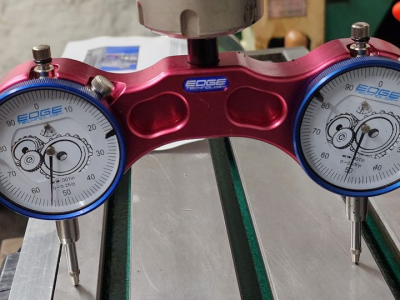
1662619090335.png

I mean, okay, technically this is NOT the only adjustment possible. I could do the adjustment bolt mod, where you drill and tap holes for adjustment bolts that work independently of the clamping bolts. But I only have like 0.0015" shims in here Maybe 0.003" in one spot. Those adjustment bolts are barely going to adjust anything, and they will dent the cast iron, and... Yeah, you get the point.

I decided to try just tightening the column bolts. Actually, I'm going to eat a pork shop first. I make the breading from scratch, and double dip them before deep frying. If I die of a heart attack because of these pork chops, it was worth it. All of this is massively off-topic, so I made the picture really small.
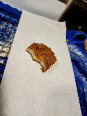
1662620220311.png

So yeah. Anyway. (Burp!) Let's try tightening those bolts.

Yeah, they're all super tight. I almost loosened them, and tried inserting a shim. You just have to make a wild guess and hope for the best. Then I decided that Younger Me would have done his level best, and he was really thorough and obsessive. Every measurement on this mill goes sloppy by 0.005" if you just measure it during the wrong moon phase. Since my tram was as good as I remember leaving it, the column nod is probably about as good as it can ever get. Using the machinist square method, the reading varies wildly depending on the height of the column. I'm pretty sure the moon phase, and Earth's relationship to Jupiter also affect the measurement.

So I fixed it a different way. Look at that! Same reading on both sides! Fixed!
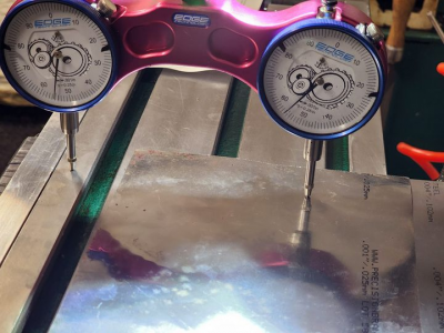
1662621484796.png
 
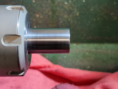
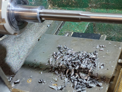
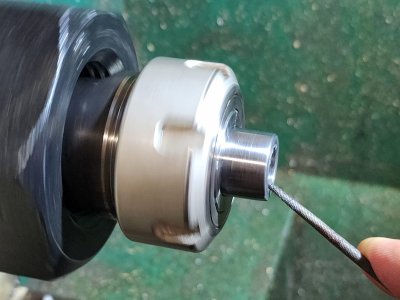
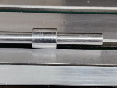
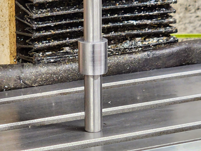
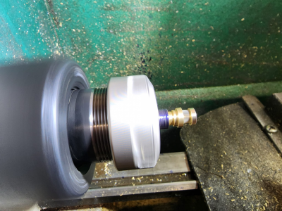
So I switched to ER32 and had to make a new system for centering my rotary table. I turned a 3/4" diameter bushing to the tightest tolerance I could manage. I cranked up the lathe to top speed and polished with oiled sandpaper (with rags covering the ways), then I drilled 27/64" I think, and reamed to 7/16". Parting left a little burr, so I chucked (colleted?) up the part to chamfer the inside slightly. My tool wouldn't fit inside the bore, so I used a needle file. Then I faced and chamfered (file + oiled sandpaper) the ends of a piece of precision ground 7/16" O1 drill rod.

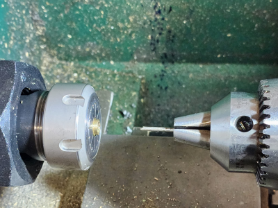
It fits tightly enough, and it's made straightly enough (the spell checker didn't underline straightly?!) to stand on its end, and the bushing doesn't drop. I don't think I could have gotten the fit any better. You don't have to press it, but it's just about as tight as you could go without having to press it. I'm going to chuck the bushing in a 3/4" ER32 collet, and chuck the pin in a 7/16" ER32 collet, then diddle the X Y cranks until the pin slips through the bushing. I think this will be good enough that I can indicate a part in the rotary table collet with a tenths indicator. Here's hoping.

1662634119662.png1662634163255.png1662634209664.png1662634285308.png
1662634334556.png
I dooded some good work today. Maybe crappy by real machinist standards, but highly excellent by truck driver liberal arts major standards. Mr. Pete was the only high school shop teacher I ever had. (God bless you, Mr. Pete!)
 
I'm not going to post the video, because I just don't want to go any deeper down the shop video rabbit hole. I hate shooting shop videos.

Anyway, I think that worked out really well. I mounted the bushing in the table collet, and the pin in the mill collet, then I eyeballed the alignment until the pin dropped in.

Then I cranked the X axis to put a little pressure on it. I left the quill loose, so when the pressure came off, the return spring pulled the pin out. It was really obvious when it hit the exact moment of optimal alignment. Repeat for Y axis, set the 0 on the DRO.

Then I moved away from 0 and carefully back to 0, and ran a tenths indicator around the outside diameter of the locator bushing. I measured something like 0.0004" TIR, at which point I decided to call it a day. I've got run-out in like ten different places, including my centering bushing itself, so adding it all up to 0.0004" seems totally acceptable to me.

I'm going to go fire up the lathe and make another one of these #@!%@#% things. I guess if I start breaking bits again, it's time to put some more shims on my column, instead of just throwing them on the table.

Since that centering pin stood on end on the mill table, I know my lathe is doing a pretty good job of facing off a square edge, and my table is pretty level. After I do the first turning, I will indicate the top of the part. On my earlier iterations of this, the top of the part wasn't even very close to level, so I expect to see a lot of improvement there.
 
Up until this point, I've known I could do better, and I wasn't taking any of this too seriously. Now I'm irritated.

For starters, here are the crappy phone videos showing my setup in action. I gently crank the axis screw, and and the instant the tension comes off, the quill pulls the pin out. Whoosh. Do the same for the other axis, and that should be close! There is a tiny amount of slop in everything, and when all that slop aligns in the most optimal way, the pin moves. That's not me forcing a pin that is misaligned with hand pressure.


Then I set up the tenths indicator on the OD of my bushing, and spun the table around by hand. I only see like 0.00035" needle movement here.

This was AFTER I set 0 on my DRO, moved away from 0, and moved back. I got under 0.0004" TIR out of this whole setup.


So my rotary table is good. Unless I'm stupid, and I'm missing something. Am I?

My lathe is good. I haven't touched anything except the ER32 nut since I got those great results.

My part was good up to this point. I was getting a great surface finish, and all my features were close enough to suit me. Maybe one feature was a little too far off, but whatever. I was willing to run with it, and proud to do so. I parted it down to this much without anything going whacky, and then I plucked it off the lathe.

1662708588305.png1662708649267.png

I drilled the center #43 hole on the mill. I started with a 3mm spotting drill, then a carbide #43 spinning at $MAX_RPM (~2000), then I chased it with a HSS #43, because the carbide drill was too short.

I couldn't tell if the hole was centered or not. It looked like maybe not. But what else could I have done here?

I was apparently no longer in picture mode, and I didn't take pictures of moving the part back to the lathe. Chucked up a #43 in the tailstock, and it slid perfectly home. Chucked it up backwards, and it impacted on the surface slightly, but I was clamping the flutes in the chuck, so, meh, not going to worry about that.

I don't physically know of any better method for checking this than to use my finest and most accurate digital dial calipers. Clamping between the center hole and that upper flange, the distance seems to vary by 0.010" or more around the part, but when I spin up the lathe, by eyeball, that center hole looks centered.

Anyhoo, installed a broken #60 carbide drill as a scratcher, blued the top of the part, and moved the Y axis 0.129" by the DRO. 0.258" / 2 = 0.129", there isn't even a tenths rounding error to consider. Cranked the table 360 with the drill barely scratching the surface.

It don't take a rocket surgen to eyeball that the drill bit scratch circle is NOT concentric with the center bore. I'm not even totally sure the center bore is concentric with the spotting drill bore. That could just be a parallax camera angle thing.

Could a 0.005" nod over 6" really cause an error this huge? I kind of suck at geometry, but I don't think so. I don't know, maybe. I got really lost in the weeds trying to figure this out. A triangle with a side of 0.005 is so many arc micro gigapixels multiplied by the pie root of square.

Anyway, at this point I am willing to drill an oversized center bore and salvage the part, if I can somehow make a hole concentric to a 0.258" bolt circle.

Or at this point, maybe I'm just trying to do too much with my Chinese crap. Maybe this is a lost cause. I have no idea how to fix this, and it's not really fun anymore.


1662708435370.png
 
When you are indicating on the rotary-table bushing, TIR looks to be ~.003” (not .0003”).

That measurement will not reflect spindle-table alignment, which would instead want you to have the indicator measure between the rotary table and spindle (e.g. using an indicol holder).

Sorry I haven’t been following all that closely - why not drill the center hole on the lathe?

Can you indicate the center-hole bore while mounted on the lathe?
 
Well, by looking at it, your rotary table wasn't centered. Check this video out he explains it well.


Also, on the drill speed personally I would slow down. I don't have a tach on my mill yet but I'm thinking a couple hundred RPM. At least that is where I would start and then go from there until it sounds good, and you start getting nice chips.

I can't help you on the nod, but I wouldn't think that would be causing the problem.
 
Take the rotary table and set it on the workbench next to the mill.
On the lathe make your part. Leave OD oversize by maybe .050 inch. finish size other features. No center hole.
With a calculator, figure out the x,y coordinates of all the hole locations for the pins. (relative to the the part center.
Clamp the part on the mill. Vblock and mill vise would work just fine.
Use dial indicator mounted in the mill spindle to get the part centered under the spindle. (use part od).
Set DRO to zero.
Spot drill, drill, ream center hole to finish size.
Dial table to first hole, x,y location. spot drill,
Move to second hole x,y spot drill. Repeat for all holes.
change to drill bit and go around the wheel again.
Remove part from mill, deburr.

Put a chunk of scrap in the lathe chuck and turn a spud to a as close a fit to the ID of the center hole as you can make it. Make spud shorter than part length.
slide part onto spud. Hold it in place with live center in tailstock.
Turn OD to final size taking small cuts so part does not spin.
Remove part and celebrate with cold one.
 
…turn a spud to a as close a fit to the ID of the center hole as you can make it. …slide part onto spud. Hold it in place with live center in tailstock. Turn OD to final size taking small cuts so part does not spin.

This sounds like a really good approach (hole locations in one mill setup then turn OD). Every time I’ve used a mandrel to turn an OD concentric with a bore, it’s worked very well. You may want to make a small piece to go between the live center and part, to give clearance and push axially without expanding the bore entrance.
 
I definitely needed the extra eyes, guys. Thanks.

All I was measuring was how well the table spins, and it doesn't spin very accurately. I never managed to check the center to the spindle at all. I just trusted my centering pin and bushing setup, and it obviously didn't get close enough.

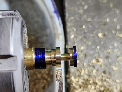
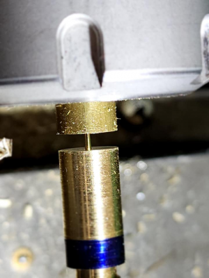
So I salvaged the bad part by sanding a brass pin until I could press it into the hole with a vise. It ran okay in the lathe. I faced off the stub of the rod, and took a skim pass that only partially removed the layout dye. The dye that remains is even everywhere, so I didn't bend the part. I got the center hole re-drilled, and I drilled it on the lathe this time. This part may not end up usable, but I'm trying. This could work. I have no idea if I got the pin all the way to the back of where this part is going to be cut off, so the back bore of the finished part might be seriously janky.

Then I indicated my vise back on the table. As well as I could. It's impossible to get the needle to stop moving, as I've seen some Youtube people do. The best achievable is the needle moving predictably, and in a tight arc. Even with a tight arc of in the neighborhood of 0.0003" it still jumps an entire 0.001" whenever I reverse direction. Cranking this way, needle hovering around 0. Reverse direction, needle hovering around 1. At least it's repeatable.

I put a brand new square collet block in the vise, and I'm going to leave it there for the duration. I think holding the part in an ER32 collet is still an acceptably precise idea. So whenever I get the OD indicated to the spindle, in about 16 to 693 hours, I will set the 0 and use the DRO to drill the bolt circle coordinates. It's that iGaging stuff and my mounting system isn't the greatest, but it seems to be holding accuracy. Here's hoping.
 
I need to spend more time honing my skills at indicating the spindle, but I got close enough for this exercise. This part was trash yesterday. I just wanted to see how far I could go.

I'm not ready to put it in the finished pile just yet, but it's a lot better!

1662792748447.png
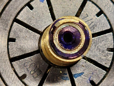
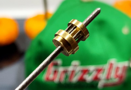
The center bore is still off slightly. It was extremely hard to center the part once I parted it off, and it was impossible to tell what the back side was going to look like until I did. I pounded another filler rod in there and re-drilled it, and it came out okay. I've built wooden clocks with lantern pinions that ran a lot worse than this, and I probably could use this in a functioning clock, if not for the major mistake I'll discuss shortly.
1662792975252.png1662793012908.png1662793120425.png1662793460266.png
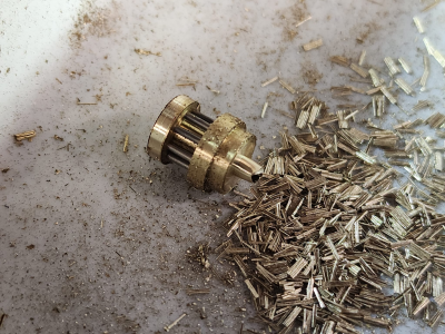
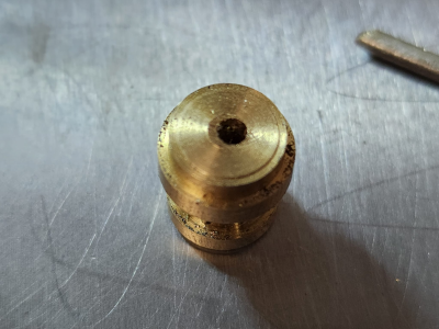
My big screw up was switching my Z axis DRO to metric inadvertently. Instead of 0.010" I was going 0.01mm, or about 0.004" into the lower shroud. A couple of the trundles (I just looked these terms up, and now I sound horologistical or something, oh là là!) just didn't seat right. It was hard getting them in there, and ain't no getting them back out. The center bore is a little wonky too.

Now I just need a coaxial indicator, a better interface for my DRO, a CNC conversion kit with balls screws to save me from backlash hell (it took forever to get the coordinates dialed in, riding the knob with one hand and dragging the table lock with the other, intentionally wearing out my gibs and ways, because it was the only way to achieve that kind of precision), or a real rotary table.

This was so much easier on a rotary table, but you can see that a couple of these pins are the slightest bit off. That was spending as long as it took to finally get the right number to hold on the DRO. I couldn't have been more accurate, and the holes were a little off here and there. My point is 0.004" slop in the table is bovine manure for a job like this, when half a thou is visibly wrong. (There are already rounding errors built right into the coordinates. That's what you get when you convert a fraction into a decimal.)

Finally, I would like to brag that I went through two bits on this, and that is only because I heard a little DINK! as I was cranking the table. Seriously?! I didn't raise the quill fine feed high enough, and I wasted a $7 bit that spent 42 seconds in the machine, and never spun once in its sad life.

The other one came through just fine though. All eight holes, and it went back into its little box.
 

Attachments

  • 1662793197207.png
    1662793197207.png
    3.3 MB · Views: 5
Back
Top