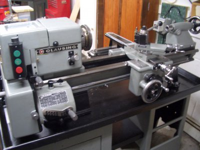
Clausing 5418 Lathe

This morning I took some steps to address the potential sources of the "squeal". First thing was to get some shaft retainer on the inboard bearing of the input shaft and get the cover back on that with the retainers. I decided between the retainers and the large gear on the outputside that the shaft should be pretty stable.

Next thing was to drop the apron and face off a 1/16" from the lead screw - that was enough to keep it off the bearing inner race of the lead screw output shaft. Cover back on that as well and lead screw re-pinned.

I also found that on the outboard side of the lead screw shaft that I had put retaining rings where the parts drawing didn't call for any. The retainers just barely fit over the nut on that end of the shaft. The nut turns with the shaft so there may have been some shifting of the retainers and interference with the nut. I decided if Clausing didn't think there were retainers needed then I wouldn't put any there. Cover back on that shaft as well.

So hopefully thise steps will resolve the squeal - I'm going to wait a while before I try i to give the shaft retainer a chnace to cure. In the mean time - I had noticed that the reversing gear set screw were vibrating loose so as long as it was apart I pulled the reversing gear bracket and put some loctite on those screws. The reversing gear bracket is mounted in the same hole as the outboard back gear eccentric and when Ipulled the bracket I found
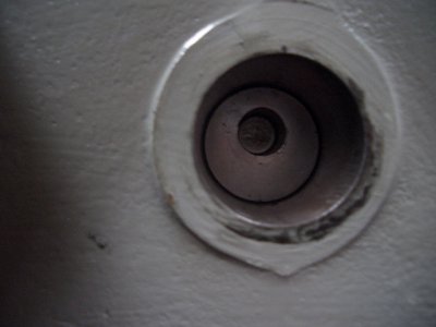
Outboard Back Gear Eccentric.JPG

You can see that bushing has a through hole and gives an access point to the back gear shaft for oiling. Pretty cumbersome to get to that but at least it is a solution. I did order the oiler and plug for the inboard bushing and will modify it to accept the oiler at some point.

Rick
 
OK. I was going to suggest that you replace the loose bearing and if the new one was still loose, install it with LokTite Bearing & Bushing Mount, or whatever they call it today.

The only difference that I see between the bench model and cabinet model headstock is some mounting holes for brackets on the back. I would have thought that if you disengaged the three belts from the jack shaft pulley and moved one to the right and the other two to the left, you would have almost the same access to the middle of the back gear as on the bench model. Difference would be the larger center and left pulley groove.

If you try to pump oil into the back gear bore through the left eccentric, it is going to require a good seal on the end of the eccentric and getting past what appears to be a pretty tight fitting shaft. The late Atlas (both cabinet and bench) is conceptually similar but the shaft is hollow with a cross-drilled hole at about the longitudinal center of the back gear. And I think larger in diameter.
 
agree - i don't like the left eccentric as a oil point - at least with the modifed right eccentric I would have an oiler that sealed and hopefully some of the oil would work its way onto the shaft. I still need to take a look at the access to the middle of the shaft via moving the belts.

the loose bearing was new - I think the shaft has some wear. It appears the shaft retaining compound is working - at least I can't move it manually. Hopefully it will be enough given the relative low speed of the application.

Rick
 
OK. Sounds like things are improving.
 
After giving the shaft retainer a day to cure - I ran the lathe today and everything seems to be fine - no squeals. I'm thinking I am at a stage where I can consider this complete - although I still have a number of things to finish. I still need to - replicate a few decals, clean up the threading dial, clean up the tool holders, clean up the 3 jaw chuck, clean up the sjogbren collet chuck, modify a SB threading stop to fit the clausing cross slide, make/buy a carriage stop and complete the three taper attachment clamp parts. MNow that I list it isounds like I still have a lot to do :).
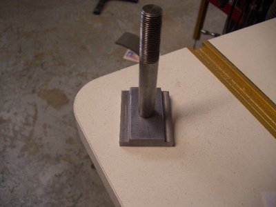
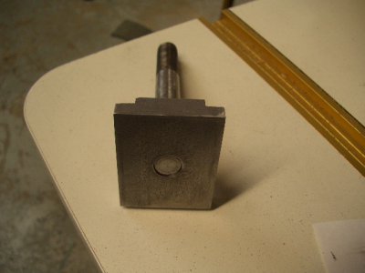
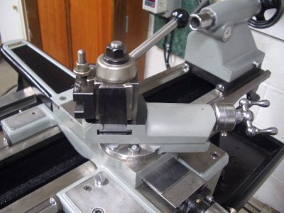
Today I spent most of time fabricating a T-nut for the QC tool post. I'm planning onusing an Aloris AXA but the T-nut was too small for the Clausing. So I got to spend some tramming the bridgeport vise, laying out some dimensions and milling the block to size. for an experienced machinist it was proibably an hour's job - for me - most of the day but I enjoyed actually using some of the machines.

T-Nut Top.JPG

T-Nut Bottom.JPG

Tool Post Installed.JPG

Overall With Tool Post.JPG
I've got the tool holders soaking right now so I should easily be able to get them done tomorrow. After that will be the collet chuck.
Rick
 
Rick,

Beautiful work! Too bad you weren't engineering this lathe back at the factory 60 years ago!

Best regards, Bruce
 
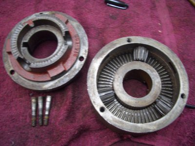
Today I'm tackling the 3 jaw chuck..It is a Burnerd grip tru (or tru grip). Up thread I was whining about not being able to get the back plate off - well I was struggling with that today until I noticed three socket head screws (not the back plate mounting screws) going sideways into the chuck body. In desperation I took them out and the back plate essentially fell off. The "screws" were actually tapered pins with a socket head and threads on one end.

All Pieces.JPG

It appears the means bear against bosses in the back plate and allow adjustment (thus Tru Grip?)? My question is how is that adjustment actually done?
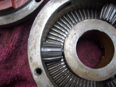
My bigger question is how do I get the pinions out of the chuck body? They push out a little but quickly reach a point where the pinion is bigger than the hole. My normal approach is too think about how these would have been put together - in this case I don't know. Unless after assembly there was some operation done to make them non-removeable?

Scroll Plate_Pinion.JPG
Any thoughts or suggestions?
Thanks
Rick
 
Last edited:
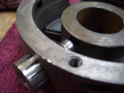
Well I got the pinions out - what I though was too small a hole in the outer chuck body was wrong. The pinions have a round section that fits in a hole in the inner ring. With a little bit of pressure the pinion started to move out through the hole in the outer chuck body. Here you can see the pinion partly removed - the inner hole in the chuck body is barely visible but its there.

Pinion Removal.JPG

I'm still curious about the process for adjusting the back plate.
Thanks
Rick
 
My 6" Pratt-Bernerd has four of what look like socket set screws equally spaced around the OD of the main body. And six socket head cap screws holding the back plate to the main body.. I presume that they each bear on one of four (your has three) bosses that are a part of the back plate. To adjust, you find and mark the high spot, slightly loosen the one or two set screws on the far side, Just barely loosen the six rear screws, tighten the screw or two screws on the high side, tighten the six screws on the rear fully, and check again. I would assume that yours is done the same except that there are only three cross screws instead of four.
 
Thanks Robert - based on my understanding of what you said - you are essentially "pushing" the chuck body around on the back plate (the back plate mounting holes are slightly oversized to alow some oment of the chuck). I'm thinking this is not something you do everytime but rather something that is periodically done using a known standard (ground bar for example)?

One more chuck question - grease or oil? When reassembling what is the preferred lubrication for the scroll plate, pinions and jaws? I seen/read cases for both but predominately it seems grease is considered too sticky?

Thanks
Rick
 
Back
Top