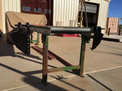
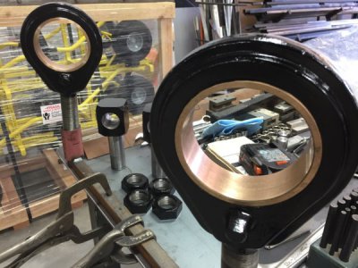
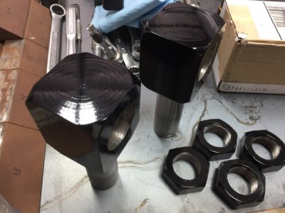
Chicago Dreis&Krump Box&Pan brake rebuild

Thanks Greg,
The hand wheels will add a little "bling" to the machine. On the struts, I knew they where there add rigidity to the base, but that makes perfect sense as they are only bolted to the main body at the top and the bottom would essentially "float"without the struts. Sometimes a guys need to step back and re evaluate or better yet, take some damn good advice from smarter folks! Thanks Greg, you just saved me some time. Now I can paint the two color scheme without separating!
 
Ah not smarter Paco, just anxious to see her properly dressed in a coat of new paint.

Greg
 
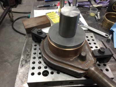
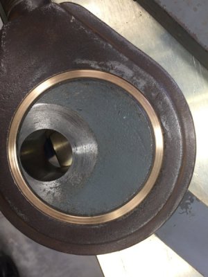
Today I presses in the new larger bushings in the link adjusters. Went pretty smooth with the press tool I made to remove the old bushings. They where tight but thats a good thing so long as the ID remains intact.

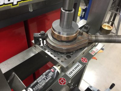
I clamped down the link flat on the set up plate and added a touch of engine assembly lube for good measure.IMG_2606.JPG
The pressing operation:
IMG_2615.JPG
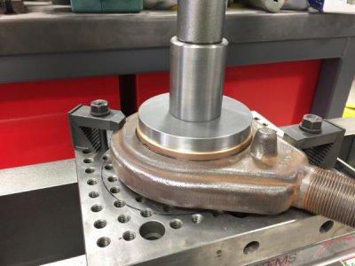
Since the bushing was so large and the HF 20T press is a little sloppy, I would press a little and release and rotate the setup to ensure a square press. Once the bushing was 1/2 in it was a final press to home.
IMG_2609.JPG
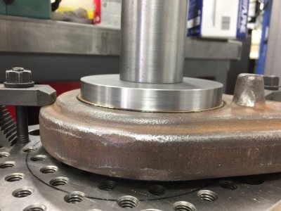
She's home!
IMG_2610.JPG
Did the second link the same way without drama.
Test fit to the lever cams proved successful. Nice and snug.
IMG_2611.JPG
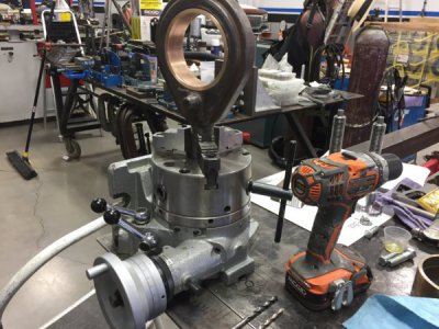
Next was to drill the ball oiler hole through the bushings. The machine was equipped with bronze bushing originally and required 30W machine oil to keep the bushings lubed. That said, theres ball oilers already in place. I drilled out the original ball oilers and use the same size drill bit to find center on the new bushing, then went down two sizes to drill through the newly installed Oilite bushing. From Previous conversation It was brought to my attention that an occasional shot of oil would flush out any smaller wear particles out adding life to the bushings. Greg (f350ca) was helpful on this topic, so a thanks goes out to him. I was able to use the super spacer borrowed from Mark (mksj) to chuck and hold the award link.
A second shout out of thanks to Mark for his generosity and trust.
IMG_2618.JPG
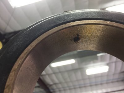
The Oilite bushings are amazing, the simple drilling operation made the bushings sweat oil.
Here you can see the the area of sweating.
IMG_2616.JPG
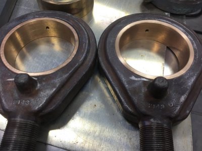
Did the second one the same way then used a counter sink to deburr the hole.
IMG_2619.JPG
Learning that very little heat/friction makes these bushing sweat got me thinking about paint. I usually paint in the sun to pre-warm the steel but this could present a problem if the steel was to become contaminated with oil. So I'll be painting in the shade.
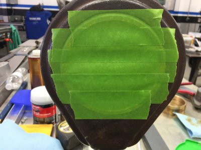
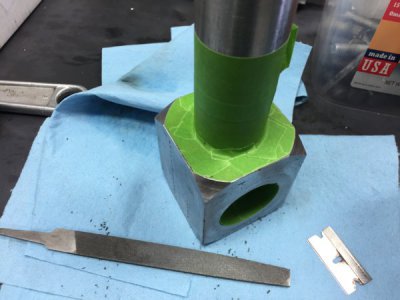
After blowing out the holes and wiping down the link, I masked them for paint.
 
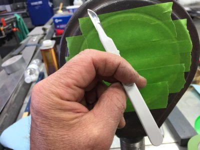
Masking went fairly quick with a scalpel and file. I've used this technique for years with good results.

IMG_2621.JPG
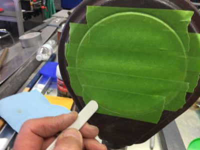
Most scalpels have a tapered handle opposite of the blade. This is handy for pressing in the tape at the joints.
IMG_2623.JPG
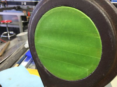
Then just follow the groove with the sharp end and your done. If you keep the overlaps of tape to one the scalpel stays sharp.
IMG_2625.JPG
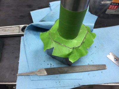
For outside corners a small file works well so long as you cut downward.
fullsizeoutput_646.jpeg
Pull off the outside portion and done.
IMG_2629.JPG
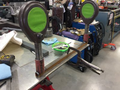
Thew together a jig stand from scrap to paint the award links and pivot blocks.
IMG_2627.JPG
Too windy this afternoon, but first thing in the morning should be calm. My plan is to shoot all moving/adjustable components gloss black as the parts require lubrication. The large levers will also be black as my hands are often dirty when fabricating. The base stand will be a silver hammer tone and the main machine will be a dark brown/copper hammer tone. The counterweights will be bright safety yellow as will be the finger extensions.
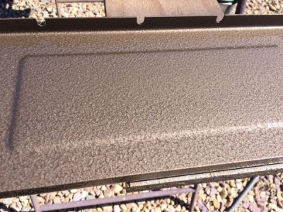
Here is a sample of the brown/copper hammer tone I used on Rockwell/Delta disc-belt sander I restored sometime back. I really like that color for machines. I've had good luck shooting Rustolium hammer tone paint and use Xylene to cut the paint for spraying using a 20+ year old HF HVLP gun.
IMG_0596.JPG
That all for today guys, Thanks for looking.
Turn and burn!

Paco

IMG_2622.JPG

IMG_2626.JPG
 
Last edited by a moderator:
Sure thing Greg, makes sort work of masking. Thanks for saving me time and $ on eliminating those struts;).
 
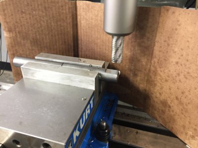
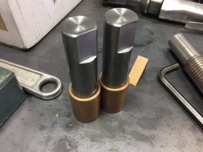
Got some paint down on a few components. While waiting for paint to dry, I turned and milled two new pivot pins for the apron. I used some aluminum soft jaws on the Kurt vise with a V groove on the fixed jaw to secure the 1" pins. Milled a .115" DOC to create a flat for the setscrews.
A short day, I took Mrs. firestopper out to celebrate her birthday.
IMG_2633.JPG
Much better fit vs the old worn pins.
IMG_2634.JPG
Main pivot/hinge for the apron leaf.
IMG_2636.JPGIMG_2637.JPG
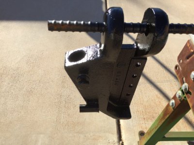
The links still need the new ball oilers pressed in but for the most part done. Nice and wet with four coats.
IMG_2640.JPG
The pivot blocks also got a wet coat as did the link nuts.IMG_2641.JPG
I'll cook them under a heat lamp tomorrow for a couple of hours. It'll take 7-10 full days for paint to cure. Tomorrow I'll work on removing the pivot block bushings I left in place to protect the bores from sand blasting. I'll turn a pressing tool for this operation. I might have an unconventional way to press out/in the bushings. Stay tuned as it will require some design work, but should work without the use of heat.
Thanks for viewing.

Paco
 
Last edited by a moderator:
Well I attempted to have more done today on the pressing tool but has a coworker stop in asking for help on his 1990 Toyota 4-runner. His front mind seal was leaking pretty bad and he tried everything to break the 18mm harmonic balancer bolt loos with no luck.

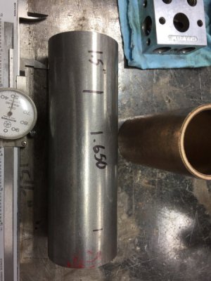
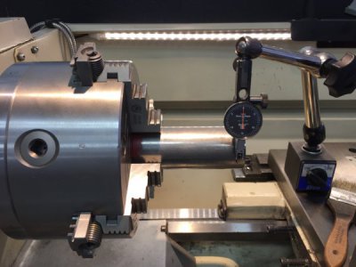
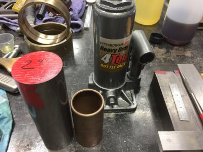
I'll start with what I did get done on the press tool.I used 2" round CR cut to 5.500" and indicated on the lathe. Faced and turned two steps. The smaller 1.5" step fits inside the bushing to be presses out and will also serve to press in the replacement. The 1.5" ensures the tool is lined up during the initial setup. The second step is .065" smaller than the OD of the bushings and 3.5" long to match the length of both bushings. The problem is the bushings are for the pivot block located in the main lower body. The work needs to be done in place
IMG_2665.JPG
The layout:
IMG_2666.JPG
Man I love this chuck.
IMG_2667.JPG
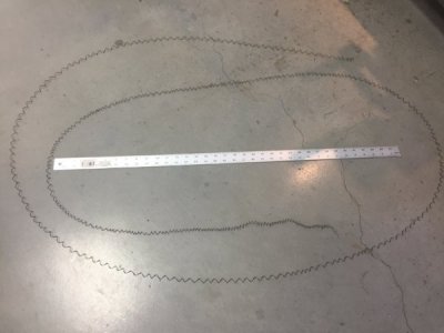
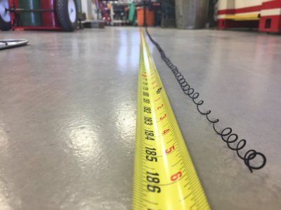
Took .040" DOC at 750 RPM with a feed rate of .009/rev so kind of fast. On the 3.5" long step the chips breaker was not working with the federate producing a continuous chip from start to finish. I made some feed changes and had manageable chips after that.
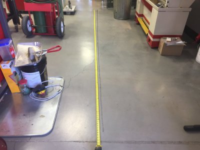
Look at this accident waiting to happen, a 15'-6" chip!
IMG_2674.JPG
The surface finish was just pretty as could be for CR, I just couldn't get comfortable with those long razor blades.
IMG_2675.JPG
IMG_2676.JPG
Anyway, the tool came out nice. The jack end was bored to fit the the shaft keeping everything lined up.
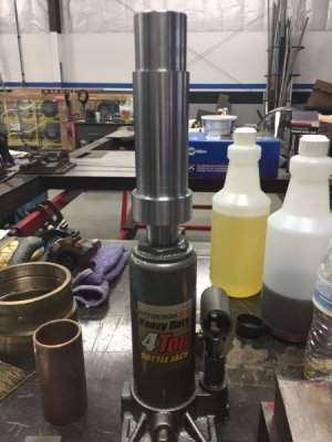
IMG_2680.JPG
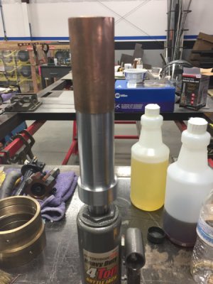
Here you can see how the bushing will be pushed against the longer stepped shoulder. IMG_2681.JPG
And lastly the bushings on main body with the tool inserted.
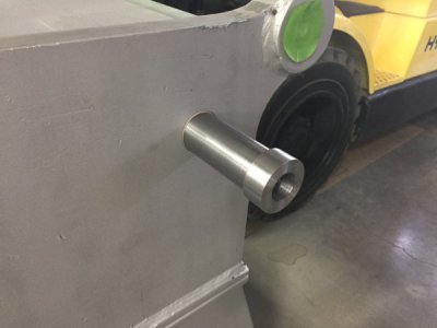
IMG_2682.JPG
So by now its clear that a solid object will be required for the jack to anchor to. The forklift will be the anchor or aka potable presso_O.

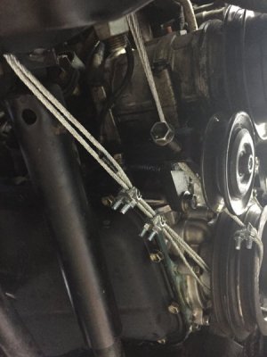
So back to the Toyota, I tried every trick I could think of to break that darn 18mm bolt including heat. Breaker bar against the passenger side frame and stater bump (coil wire disconnected) My big A$$ impact with 130 PSI set on #5 for max. Nothing was working including a 48" cheater on a 3/4" breaker bar. It seemed we where just turning the engine, Yes, it was in gear and e-brake set, but the darn crank was rotating. Then the light bulb went off in my minds eye. I needed to restrain this damn thing and I remembered I had some aircraft cable left over from hanging the shop ductwork. I also had three cable clamps. I threaded the cable through the harmonic balancer and around the passengers side frame three times. Using two clamps on the bottom and one on the top three layers. Grabbed the 48" cheater and pulled, I thought The bolt head had broke but it was the bolt breaking loose. The owner had been spraying penetrating oil for the past week but the large built in washer prevented a direct shot.
I wanted to share the set up with anyone interested incase you find yourself in the same bind. It worked well and the front seal and oil pump O- ring replaced.
Looking from the top.
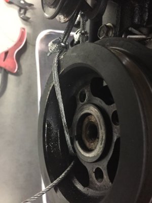
IMG_2677.JPG
Bottom view. No way the crank can turn CCW allowing the bolt to be removed.
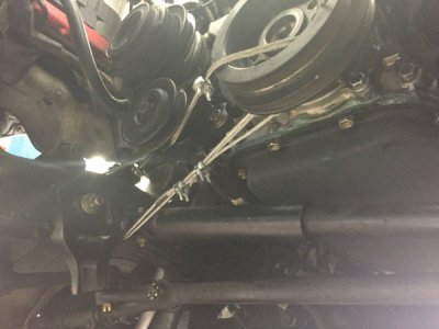
IMG_2679.JPG
IMG_2678.JPG
Thats all for now fellas, thanks for viewing.
New machine arrives tomorrow, I'm so excited, don't think I'll sleep a wink tonight:grin:.


Turn and Burn,

Paco
 
Last edited by a moderator:
Nice job (on EVERYTHING !!). :grin:

I'll remember that lashing the balancer.
 
Last edited:
Thank you extropic,
Lashing is the word I needed for a better description. Restrained sounds better in my EMS reports when I have a combative patient but Lashing sounds way cooler for this application. My bosses would s**t if I used "lashed the unruly patient" but as a short timer I might need to try it hahaha!
As always, good feedback is always welcomed.:)
Be well,
Paco
 
Back
Top