Calculating shear strength of bolts on corrugated roads

To add a thought here - a long time ago I owned a Ford pickup - a 1955.

The tank in that was supported in a cradle - the cradle bolting to the chassis. Think a set of L legs - the long side bolted to the frame.

The tank was then supported on the other side of the L, and its mount to the L and the chassis was steel strapping.

Admittedly parasitic weight, but that bugger was NOT going to get loose as long as the though bolts to the chassis held.

I shook a lot of bits off that truck in some fairly inhospitable places, but the tank was never a worry.

Just my two penn'orth - Alan.
 
I didn't look up the shear strength of grade 5 vs. grade 8 bolts so just guessing here off the top of my head. Shear is force per unit area. Back in the day, we'd estimate up to a 30g load because of extremely rough roads or 30 times the weight being supported. An extreme pot hole was only 10 g because it was a one-time event,

Calculate your cross section area of the bolt(s) and divide that into the weight being supported. Again, available on-line with a quick fact check, but grade 5 bolts are probably good for around 100,000 psi. Grade 8, maybe 150,000 psi.

Bruce
 
Bruce, that was the sort of figure I was looking for. I didn't think it would be that high, but would prefer to have a few extra bolts than not enough. The plan was always to have a rubber mount which would allow for some chassis /tray twist - just trying to work out the best way of applying the help that the group have passed on to me. Much appreciated.
The weight of the fuel will be approximately 145kg plus the weight of the tank which I estimate will be probably about 60kgs - so a 200kg dead weight. 30 times that is 6000kgs momentum. It sure adds up.

Here is a quote from another source about this matter.

"For an M12 bolt on the thread I'd use 10mm as the bearing area to be safe.
Allowable bearing force on 12mm mild steel plate with a bolt diameter of 10mm would be 2.06 tons according to the table I have, 12mm shank/pin would be 2.47 tons. The shear strength of the bolt will far exceed the bearing capability as even an 8.8 rated M12 bolt would have a shear strength of 4323 kg.
The table I'm using has a safety factor of 5 which is the lifting industry standard rather than 3 which some non critical applications use."

So If this is true, then I don't need a dozen 10mm bolts to support 30 times the weight - however I still need to design the interface (straps or what ever) that connect the fuel tank to the tray. I had better go and do some more thinking.

Thanks again to all.


Mal
Hi Mal,

Not a problem. We used 10g for FMVSS 208 standards on things like console arm rest lids. Weigh the armrest and pull up with that force. If it stayed closed we were good to go. That was in the 1990's so don't know if the old validation by calculation still holds true.

One of the Milford Proving Ground engineers told me for suspension parts on military vehicles (Hummers) they used 30g which seems high. But if it was my kid in harm's way, the bigger the safety factor the better.

Bruce
 
The secret with corrugated roads is to drive fast enough so that the wheels only hit the tops of the ridges.This is how big trucks survive on the roads......If a truck slows ,the corrugations twist and work the chassis and axles to failure in a short time.
 
Thanks Bruce. I am busy redesigning the mounting points to make sure there will be no interference when the tray with tank is fitted to the Toyota. Better to have lots of planning before our fabricator starts to knock up the actual parts in metal.

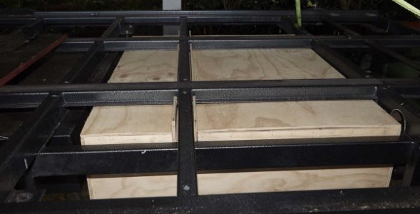
Attached is a plywood mock up of the diesel tank to be built. Yes it will be tweaked but this is the opening iteration.

MalMAL_0182.jpg
 
I suggest you look at a phone app called "IEngineer". It shows the strengths (including sheer) of all common sizes and grades of bolts. I use it frequently as it also shows drill size and a lot of other pertinent data. I believe it is free for imperial sizes and a minimal cost with the addition of metric. Give it a try - I don't think you will be disappointed.
 
Mal you might also consider using resilient mounts, as commonly used in mounting machinery, they are designed to absorb these cyclic vibrations.
 
Mal you might also consider using resilient mounts, as commonly used in mounting machinery, they are designed to absorb these cyclic vibrations.

Bob, I am open to all suggestions - I will do a search and see what I come up with.


Thanks Mal
 
Back
Top