Bad surface finish 6x12 surface grinder spindle disassembly questions

I reground the chuck on the surface grinder. The finish is better then previously, but still has some ripples from wheel balance, I believe.
I found this needed (grinding the mag chuck) as I was grinding a 1" plate flat, about 4x8 rectangle. I need this to stand a part (the top slide off the lathe compound) off the mill table.
I was measuring 0.9411 to 0.9416. I did find a shallow part on the magnetic chuck. So I reground the plate and now have 0.9382 everywhere I can reach the micrometer in from the edges. It took over 8 grinding passes on the chuck to make it flat. As I'm grinding without coolant, I have to keep the material removal to less the 0.0002, or it will get hot and swell, and leave burnt iron.
And yes I need to install the feet that came with the surface grander and sitting on the bottom shelf, as I see the thing is rocking.
Looking good!
In the videos it looks like your machine is rocking back and forth. From everything I've read surface grinders need to be rock solid as and vibrations are going to show up in the finish.
 
Looking good!
In the videos it looks like your machine is rocking back and forth. From everything I've read surface grinders need to be rock solid as and vibrations are going to show up in the finish.
Standing in front of the machine, I didn't see the rocking. I did move it 8 inches from where it was, as the table was hitting the O-A torch that the camera was mounted on. It's just enough weight to make installing the feet a job. It's cold in that part of the shop, and I'm in tropics compared to weather to the north. But it is just above freezing in that garage space. I keep the grinding tools away from the lathes and mills.
I'm going to make the wheel balance adapter outlined in this link;
I have the accelerometer (MMA7361) ordered, that I hope will generate enough signal to measure the 3450RPM vibration. We shall see what I learn. I also have a fancy oscilloscope I've never used the fancy math functions on, and will see if a FFT will give me some value for the 60Hz wheel vibration.
But now I need a precision balance, always need another tool........
 
The previous day, I was grinding the plate, I was shocked that I had to grind so much to make it flat. I had fly cut the mill scale off the hot rolled steel this plate came from. I had freshly trammed the mill. The mill is worn a bit, it's a 645 Wells Index. This was before I had tightened the gibs, as I hadn't never done that before. And they all were very loose. So it would be interesting to machine another plate to see if it requires less grinding to make it flat.
I use a 0.0001 indicating 2 inch travel indicator I got off ebay many years ago to control down feed on the grinder. The mechanical scale on the machine never produces any controllable down feed. They guy I got this indicator from worked as a technician for some USA service center. After I purchased this, he told me that it was originally only at .001 indicator, but he knew where on the board to cut and jump to enable the .0001 operation. If there is some accuracy issue with the scale, I've never seen it. It would be handy to have a 0.00005 digit, or better readout, as .0001 can be too much material to remove, in a controlled way.
 

Attachments

  • What drove the regrind of the mag chuck.mp4
    1.1 MB
  • 10.8 thou to make it flat.mp4
    2 MB
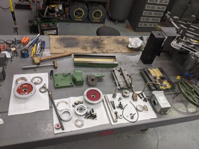
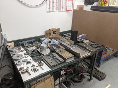
Sorry Taper, my day job gets in the way a lot. Also, I finally managed to get a set of Kennedy boxes for my precision tools. Since I bought a lathe a year and a half ago, the tool situation has been getting out of control. Good problem to have. Also, I have taken my surface grinder *all the way apart. I am now, ironically, grinding down the rough castings for better appearance. :D I have started a new thread on the motor rewind. It's a lot of work, not done yet.

I know exactly what a FFT is, a Fast Fourier Transform! My education is as an EE. I've not heard about FFTs in a while, I'm very interested to see what you get. I would be willing to bet that you get nothing but 60Hz and harmonics of 60Hz. I guess the real question there is: can you convince yourself that the surface finish is a 60Hz pattern? It almost has to be, any way you slice it. The induction motor is driven by 60Hz pulses, it is the primary source of any vibration (hopefully ;)). Also, can you convince yourself that wheel balance is allowing those vibrations to cause a significant movement of the wheel or table? Maybe? Probably? But, the important thing, and I'm sure the reason you're doing it, is you will have a feedback system. Then you can play the change the balance and see if the amplitude of the vibration is lowered game; attenuate the signal.

Although never good, vibration in and of itself is not necessarily bad. After all, a good design should allow that to be averaged out in the business end. Unless it results in a standing wave, aka natural harmonic of the system. As in resonance. It will be very interesting to see if the predominant frequency is not 60Hz but a multiple of it. Changing the balance of the wheel should produce a measurable difference in the output of your transducer. Note, though, you may need an amplifier for that transducer.
 
There was also a recent question about unwanted z-axis movement. So I figured I would put a bit here about that. Before I took mine apart I was getting some very surprising, and occasionally exciting, unexpected z-axis movement. On the order of a few (maybe more) thousands. I attributed this to the machine being old a crusty and the ways must be dirty. I addressed this by using a small deadblow to tap on the z-axis slide, and that "fixed" it. Right. When I took the machine apart I found the real issue.

The column of the machine is not just a structure for the motor and z slide to sit on. It also houses a counter balance. This is certainly because this machine is "direct" drive and the weight on the z-axis acme nut, made of bronze, would be rediculous without it. However, the design of the counter weight system on mine (80's) is just bad. Not just poor execution, badly designed. It is also poorly executed.

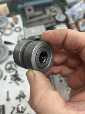
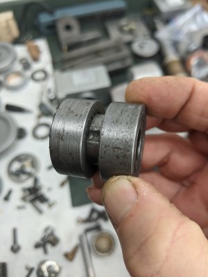
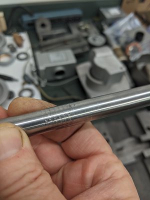
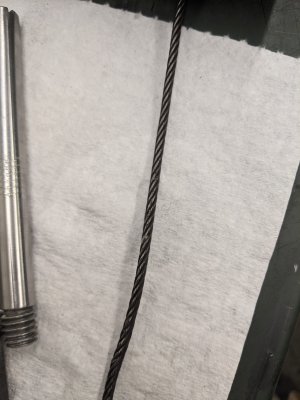
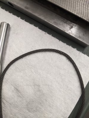
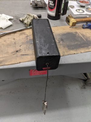
The counter weight is a brick of cast iron. A cable attaches to the top of the brick. There is a fine finished, poorly heat treated, 1/2" diameter shaft that goes through the front of the column and screws into the back of the column, near the top. On the shaft sits an axial bearing with a collar pressed onto each end forming a crude bearing. The cable drapes over this and goes through a hole in the column into a bushing pressed into the z slide base, and then draped down over a small diameter hardened dowel pin, and then attaches to the bottom of the z slide...... Neat.

Seeing this made my inner engineer scream a little. The axial bearing housing has four flats on it...... /hand-to-forehead Seriously?!?!? Yes, seriously. First off, an axial bearing is a total misapplication. There are axial bearings that can take rotational load. This is not one of them. Add to that the ball bearings are less than a 1/16th in diameter and ride on a fine finished 1/2" diameter shaft. How do I know the shaft is poorly heat treated, if at all? It's all the dents and bearing trails that give it away. Add to that the minimum bend radius of a less than 3/16 cable, which is around 2", bending over a 7/8" diameter "pulley" and a maybe 3/16" diameter hardened pin. And then, finally, did I mention the pulley with FOUR FLATS ON IT!!! (Insert nerd rage here)

It's just a bad design. The ball bearings dig into the poor bearing surface, which allows the cable to drag over the hard edged flats and then over a hard pin. At least the pin is round I guess. This has caused the cable in mine to become shinny and flat in one side, and severely abraded. This allows the z-axis slide, with all that weight, to hang on traversal and jump when, well, whenever. I have a solution to this, which, while not perfect, does not involve flats on a square shouldered pulley. A better solution would involve 2"-ish diameter pulleys, but that would involve moving the axis of the pulleys out of the z slide base and out of the column.

On a related note, whoever assembled my machine, if you're listening, please stop using so much loctite. Or at least switch to blue. Blue is just as tasty as the real thing and would allow for disassembly of things without the use of magic bullets. If anyone is interested in how to get the cable detached from the counter weight with the use of carbide drills, let me know, it's quite the contraption.
 
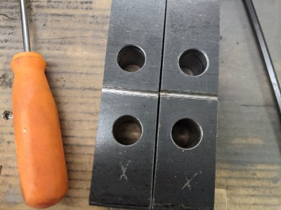
So how did you remove that broken cable with the ferrule?
I know that when I got this delivered via truck, the cast iron counter weight had broken free. I just don't remember how I fixed this. I purchased the stand at the same time, it has a hole punched in the top for the weight to travel down through. I just realized that, and moved all my spare grinding wheels to the bottom shelf, just in case it lets loose to smash them. Darn things are expensive.
 
So how did you remove that broken cable with the ferrule?
To be clear, I broke the cable.
PXL_20210131_033113039.jpgPXL_20210131_185218205.jpgPXL_20210131_191131212.jpgPXL_20210131_201316219.jpgPXL_20210131_201655033.jpg

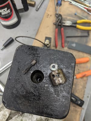
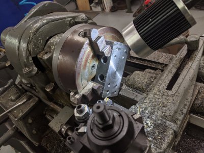
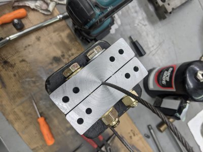
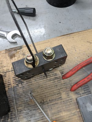
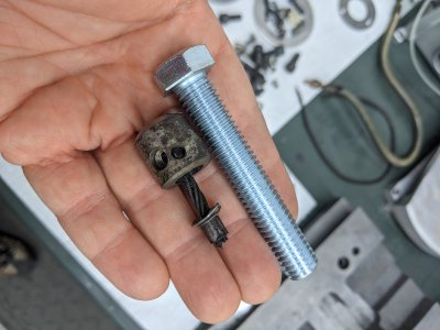
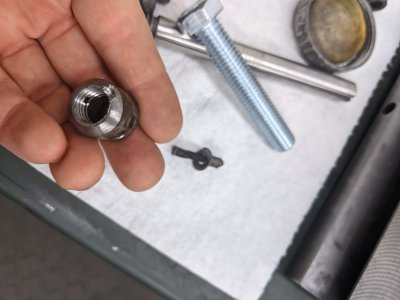
After removing the set screw in the block for the cable clamp, the clamp assembly would *not come out. I figured it might be threaded into the block, which it was, but there is nothing to grab to turn it. After failing with heat with a chisel and hammer I made my own cable clamp. I succeeded only in riping the cable in two. I mean... Plus one for making a good cable clamp. The reminder involved a carbide drill bit, the progressively larger drill bits, then a 1/2-13 tap. Coincidentally 1/2-13 is exactly the thread into the block itself. So the act of drilling the cable clamp to 27/64 broke the connection between the main part of the cable clamp (with more set screws, hence the need for the carbide bit) and the threaded part of the cable clamp. All that remained was the ridiculous amount of loctite on the sides of the cable clamp. The act of taping it finally broke it free and it just fell out. Guess I should have used more heat. I was being very careful and managed to not touch the threads in the block.
 
Last edited:
PXL_20210214_184340982.NIGHT.jpgPXL_20210214_184424884.NIGHT.jpg
Just imagine a 1/2-13 thread in that missing section of that cable clamp, like the 1/2-13 bolt next to it. Then try to imagine how lucky I was. Drilled right down the center and didn't touch the threads. Also note the top 1/64" of a set screw still in the cable clamp. No point playing the lottery this month, used all that luck up.
 
Back
Top