- Joined
- Feb 1, 2021
- Messages
- 14
Well, I'm a little late to the party here. My apologies for not posting here sooner, but I just found this post today 

As fate would have it, I happened into one of these as well. I believe mine was originally an Emco from the early 80's. I cannot prove that because at some point in it's life it went to a tool wholesaler who cleaned it up and completely de-badged it, including the motor plate (more on that later). Before I dive into the insanity that followed, a quick bit about what I found out about these machines.
First, although I have not found the original design or manufacturer of these machines, there are a *lot of them out there. These got rebranded as a lot of familiar manufacturers. Enco, MSC, Grizzley, Tormach, Phase, Palmgren, Jet, and Dayton. There are probably others. The real model number is "MJ7115". Just google "MJ7115 surface grinder" and you will see what I am talking about. Lots of Alibaba hits to manufacturing plant in China. Basically companies that are trying to hit a price point in their equipment line up will white box these straight from China and then OEM them as their own. Common marketing tactic. The one from Tormach is pretty neat, they added some automatic power feeds to the X and Y axis.
I bought mine off of Craigslist here in norther VA. The guy was asking $500, said it had a bad "magnetic switch". It was in a storage unit, so no "trying it out". I offered $400 and he accepted. Got it home, up on a stand, and then figured out the motor was burned out. Long story short, the guy gave me my money back and and let me keep the machine, probably because he didn't want to move it.
Also making a very long story short, I rewound the motor. That's harder than it sounds when there's no number plate. I will start a thread on this site about that if people are interested. Bottom line, these things are hard to get parts for. The motor is a purpose built motor, so unless you can get one from the factory, there is not other replacement. Grizzley *does have one, but they would not send a picture. So, $120-ish (and three tries) later and I have a re-wound motor.

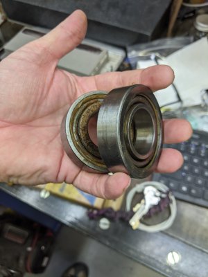
In that process, obviously, I had to disassemble the bearings. As you discovered, there are two in the nose bell housing and a single 6000 series double shielded bearing in the end bell housing. It's interesting that your's came with 6206 deep grove sealed bearings. Mine did not. Mine came with open (not shielded or sealed) 7206 40 degree angular contact bearings (with no ABEC ratings). I did not take a picture of the markings, but my recollection is that they are FAG 7206B made in Germany and have an eccentricity mark. The 6000 series was made in Japan (I can't remember the exact number, but the machine has 3 or 4 of them, all the same. Given that I was not able to find a precision rating, let alone an ABEC rating, I'll be replacing the bearings no matter what. There is no safe way to remove these bearings without putting pressure on the raceways through the balls. When I reassembled the motor, I over packed the hell out of the bearings. I really didn't care at the time as I was most interested in seeing if I rewound the motor correctly or it was going to catch fire. Started out with an isolation transformer with variac, but eventually I had to flip the switch. Turns out I wound it correctly. So I threw it back on the machine and started grinding using my rusty magnetic chuck.
Before I get into that, a Word on the machine I picked up. I have no idea how good the quality is on these machines now, but mine, from the 80's, is all over the place. Well made expensive components throughout: bearings, fastener are well made and mostly (but not all) English thread, Mag chuck is made in England, actual brass nuts on the hand-machined T-bolts for the cast aluminum clamps, hand scraped ways. Well designed features are found all over too: gibbed ways, compensating lugs for the lead screws made of what appears to be real copper, motor starter (for all the good that did), dual voltage motor, z-axis counterweight with a crazy cable and pulley contraption. Actually, that last one... terrible design. I will be redesigning it. And then there are the really rough castings. The slot in each gibb that was obviously cut by hand with a angle grinder. Hand scraped ways, but no flaking, that would be expensive. Flaking on top of the table where nothing will ever touch it, but no hand scraping there. Precision surfaces that were hit with an angle grinder and then machined. All in all, precision and high-end components where it needs it, poor execution of a good design elsewhere. But generally good bones.


So, surprise surprise, it worked. Ground a hardened washer to withing 5 tenths on the first go. Bad surface finish though.... Hmmmmmm.... Could be spindle bearings. Could be an inappropriate grinding wheel. Could be a poorly dressed wheel. Could be my nearly non-existent technique. Could be all the above. So I ground a couple more pieces, watched a few videos, dressed the wheel properly, and then ground a few more pieces.

Manages to get a T-nut to be 2 tenths of parallel. Still a bit of pattern if you hold it in the light right, but way better.

Also ground a 3/32 drill bit to .0520 flat, within 1/2 a tenth end to end over 2". The spindle bearings are generating heat from being over packed, but not excessive. Measured the run-out on the spindle shaft at less than a tenth, after taking the motor all the way apart and putting it all back together.


Things were working well enough that I feel like I can justify rebuilding it. It is now almost completely disassembled and most everything has been de-greased, de-rusted, and blasted with urea ascetate (plastic) media. I have some MRC (SKF) matched 7206 DS ABEC-5 bearings coming from ebay as well.
As fate would have it, I happened into one of these as well. I believe mine was originally an Emco from the early 80's. I cannot prove that because at some point in it's life it went to a tool wholesaler who cleaned it up and completely de-badged it, including the motor plate (more on that later). Before I dive into the insanity that followed, a quick bit about what I found out about these machines.
First, although I have not found the original design or manufacturer of these machines, there are a *lot of them out there. These got rebranded as a lot of familiar manufacturers. Enco, MSC, Grizzley, Tormach, Phase, Palmgren, Jet, and Dayton. There are probably others. The real model number is "MJ7115". Just google "MJ7115 surface grinder" and you will see what I am talking about. Lots of Alibaba hits to manufacturing plant in China. Basically companies that are trying to hit a price point in their equipment line up will white box these straight from China and then OEM them as their own. Common marketing tactic. The one from Tormach is pretty neat, they added some automatic power feeds to the X and Y axis.
I bought mine off of Craigslist here in norther VA. The guy was asking $500, said it had a bad "magnetic switch". It was in a storage unit, so no "trying it out". I offered $400 and he accepted. Got it home, up on a stand, and then figured out the motor was burned out. Long story short, the guy gave me my money back and and let me keep the machine, probably because he didn't want to move it.
Also making a very long story short, I rewound the motor. That's harder than it sounds when there's no number plate. I will start a thread on this site about that if people are interested. Bottom line, these things are hard to get parts for. The motor is a purpose built motor, so unless you can get one from the factory, there is not other replacement. Grizzley *does have one, but they would not send a picture. So, $120-ish (and three tries) later and I have a re-wound motor.
In that process, obviously, I had to disassemble the bearings. As you discovered, there are two in the nose bell housing and a single 6000 series double shielded bearing in the end bell housing. It's interesting that your's came with 6206 deep grove sealed bearings. Mine did not. Mine came with open (not shielded or sealed) 7206 40 degree angular contact bearings (with no ABEC ratings). I did not take a picture of the markings, but my recollection is that they are FAG 7206B made in Germany and have an eccentricity mark. The 6000 series was made in Japan (I can't remember the exact number, but the machine has 3 or 4 of them, all the same. Given that I was not able to find a precision rating, let alone an ABEC rating, I'll be replacing the bearings no matter what. There is no safe way to remove these bearings without putting pressure on the raceways through the balls. When I reassembled the motor, I over packed the hell out of the bearings. I really didn't care at the time as I was most interested in seeing if I rewound the motor correctly or it was going to catch fire. Started out with an isolation transformer with variac, but eventually I had to flip the switch. Turns out I wound it correctly. So I threw it back on the machine and started grinding using my rusty magnetic chuck.
Before I get into that, a Word on the machine I picked up. I have no idea how good the quality is on these machines now, but mine, from the 80's, is all over the place. Well made expensive components throughout: bearings, fastener are well made and mostly (but not all) English thread, Mag chuck is made in England, actual brass nuts on the hand-machined T-bolts for the cast aluminum clamps, hand scraped ways. Well designed features are found all over too: gibbed ways, compensating lugs for the lead screws made of what appears to be real copper, motor starter (for all the good that did), dual voltage motor, z-axis counterweight with a crazy cable and pulley contraption. Actually, that last one... terrible design. I will be redesigning it. And then there are the really rough castings. The slot in each gibb that was obviously cut by hand with a angle grinder. Hand scraped ways, but no flaking, that would be expensive. Flaking on top of the table where nothing will ever touch it, but no hand scraping there. Precision surfaces that were hit with an angle grinder and then machined. All in all, precision and high-end components where it needs it, poor execution of a good design elsewhere. But generally good bones.
So, surprise surprise, it worked. Ground a hardened washer to withing 5 tenths on the first go. Bad surface finish though.... Hmmmmmm.... Could be spindle bearings. Could be an inappropriate grinding wheel. Could be a poorly dressed wheel. Could be my nearly non-existent technique. Could be all the above. So I ground a couple more pieces, watched a few videos, dressed the wheel properly, and then ground a few more pieces.
Manages to get a T-nut to be 2 tenths of parallel. Still a bit of pattern if you hold it in the light right, but way better.
Also ground a 3/32 drill bit to .0520 flat, within 1/2 a tenth end to end over 2". The spindle bearings are generating heat from being over packed, but not excessive. Measured the run-out on the spindle shaft at less than a tenth, after taking the motor all the way apart and putting it all back together.
Things were working well enough that I feel like I can justify rebuilding it. It is now almost completely disassembled and most everything has been de-greased, de-rusted, and blasted with urea ascetate (plastic) media. I have some MRC (SKF) matched 7206 DS ABEC-5 bearings coming from ebay as well.