Bad surface finish 6x12 surface grinder spindle disassembly questions

It's been so long, I don't remember how I fixed the cable, or what that assembly looks like. I guess I'm going to have to pull it apart to see about drilling and tapping for a slide lock on the vertical slide. I recall the brass threaded nut that was used for the height adjust, and it being damaged. I know I didn't have a tap to make a new one. There was some sort of backlash screw adjustment.
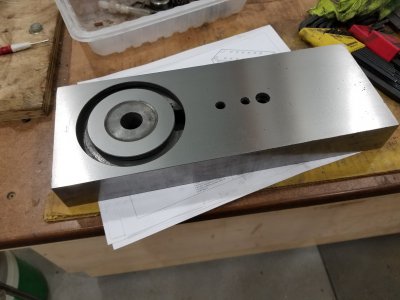
My infeed cross axis has a horrible squeal and I had worked on it. The retainer plate;
from your photo above;
surface grinder retainer plate.jpg
They made this part from scrap aluminum, you could see the silk screen from a sign it came from. It with too thick, to fit under the crank, so they hammered it in place to thin it out. I know your's was put together better, mine has no thread lock. Which is good, as I hate twisting the heads of of cheap hardware.

So you say 1/2x13, Tiawan must have been using SAE fasteners in the 80s. My 1976 Jet lathe made there was all metric except the threading and cross feed screws.
 
I know I'm late to this discussion....

I have the Central Machinery surface grinder and wanted to show you how capable it is in surface finish.

This a cast iron compound slide from a Monarch 10EE lathe.

Within 1 tenth of entire surface.

Full disclosure, I rebuilt the machine, scaping in all surfaces and a new motor bearing. Original spindle bearings.

The worst part of the machine was the table and saddle Vee and Flat ways. Horrible fit. You can see by bluing the table ways and making a "print" onto the saddle ways. You'll be lucky to get more than 30% contact. It is very important to achieve as close to "100%" contact as possible because when the table is traversed side to side you want even and constant contact pressure under the grinding wheel. I can take off 0.002" per pass with a 0.050" in feed working in both climb and conventional directions. This would be the maximum depth of cut for this machine. I usually take 0.001" per pass and finish with 0.00025" pass.

BTW I discarded the counter weight in the column. After I scraped in the Y axis slide and ways I didn't need it. There is no discernable difference in raising or lowering. I was all set to install a small gas shock from Ebay, but never needed it.

I also repainted it and wired in a E-stop and push start magnetic contactor. The rocker switch is for the LED work light.
Compound Slide 1.jpg
 

Attachments

  • compound Slide 2.jpg
    compound Slide 2.jpg
    287.9 KB · Views: 24
I know I'm late to this discussion....

I have the Central Machinery surface grinder and wanted to show you how capable it is in surface finish.

This a cast iron compound slide from a Monarch 10EE lathe.

Within 1 tenth of entire surface.

Full disclosure, I rebuilt the machine, scaping in all surfaces and a new motor bearing. Original spindle bearings.

The worst part of the machine was the table and saddle Vee and Flat ways. Horrible fit. You can see by bluing the table ways and making a "print" onto the saddle ways. You'll be lucky to get more than 30% contact. It is very important to achieve as close to "100%" contact as possible because when the table is traversed side to side you want even and constant contact pressure under the grinding wheel. I can take off 0.002" per pass with a 0.050" in feed working in both climb and conventional directions. This would be the maximum depth of cut for this machine. I usually take 0.001" per pass and finish with 0.00025" pass.

BTW I discarded the counter weight in the column. After I scraped in the Y axis slide and ways I didn't need it. There is no discernable difference in raising or lowering. I was all set to install a small gas shock from Ebay, but never needed it.

I also repainted it and wired in a E-stop and push start magnetic contactor. The rocker switch is for the LED work light.
I also reground the top of my compound on a horribly built grizzly 18x40 I purchased in 2004. The top was not flat. They 'fake' scraped the area where the tool post mounts, and the rest of the compound had a shallow concaved surface. The major fix was the side was not parallel to the dovetail slide, and I'm trying to use a sine bar to set the angle for precise grinding/machining angles.
I just fixed the headstock taper adapter, this has a 90mm metric taper OD, and a #4 MT hole for a center. It was made incorrect from original delivery, and rocked in the headstock.
Sounds like you did some major improvements. I still see surface ripple in the things I grind, but they are flat to better then a tenth.

Video of me seeing how non flat the top of the compound is. It had nothing to do with the unsupported dovetail. Also note the scraped surface where the tool post mounts, this is not flat.

Grinding the top of the compound flat after machining on the mill to remove the concaved surface.

photo of top compound slide installed back on lathe. I'm still having surface finish issues, but it is flat within a tenth.
 

Attachments

  • 20210218_203241.jpg
    20210218_203241.jpg
    3.2 MB · Views: 22
Last edited:
You can see by bluing the table ways and making a "print" onto the saddle ways. You'll be lucky to get more than 30% contact.
View attachment 357960
I don't have scraping tools. Did you just use the table against the saddle to print the mismatch? I don't have the straight edge needed, but if you did this with just the two machine components against each other, I can at least see how bad my machine is.
What is the year of manufacture of your machine? I assume they got worse over time.
I find that any heavy cuts cause so much heat that the iron expands upward into the wheel and burns, and then leaves a hollow when it cools. I'm trying to figure out how to get a coolant tray under the chuck so I can keep the mess down, but use a mist coolant.
Date of Manufacture: 01/1996
What you want to do is remove all oil/grease/dirt from all of the way and slide surfaces. I use lacquer thinner or acetone. Then use a flat stone and lightly rub each surface to remove any dings or burrs. Wipe again with lacquer thinner or acetone. If you are using oil based Prussian blue, put a dab on a flat plate and work it in with your finger. Then apply to the table Vee way and flat way. Spread a nice even thin coat. Work it with you finger. Then place the table on the saddle straight down on the ways not sliding on either side of Vee way. Then move the table side to side no more than 2" in each direction. Pull the table off and look for blue areas on the saddle ways and also wiped off areas on the table ways. Remember you want full contact on all of the flat way and Vee way. The vee way will be tough to see because the saddle vee has an oil groove cut into each side.
I learned some scraping from my grandfather. I use old files ground with a slight radius on the nose. Needs to be sharpened on every cycle of scraping but works well. My Vee way was so bad that I had to cast Moglice in the Vee and scrape to finish.

Yeah, any cutting deeper than 0.002" on the CM grinder is really tough on it. I don't use coolant. Never needed it and I have been grinding with the CM grinder for 5 years.
Thank you for this. I've used "High-spot" mainly on tapers to check fit. When it gets warmer here, I'll have to try to see what condition the ways are.
Last week I did take the table off, and clean the face of the surface, as out in the garage where this machine is kept from my lathes and mills, it was down to 35F. And I could barely move the table back and forth. I have not had this table off since I purchased this mail order new from HF back in 1992 or so.
I've been working on it as I have a series of projects where I need a very flat surface. But in the past it has always performed adequately, but I've always had this ripple surface finish.
I did some more work on it today, as when I put a tenths indicator on the spindle grinder hub taper, I was seeing a few tenths runout.
 
So after putting new bearings in the spindle, I was still seeing runout on the grinder hub taper. So this morning I took the motor spindle off the machine. Installed it on my lathe. The motor shaft end where the TEFC fan mounts I put in the 6 jaw lathe chuck. The other end I supported in my steady rest. I initially held the shaft concentric to the lathe spindle with a center in the tail stock, and then adjusted the steady rest to hold this position.
I have a video of that setup.

Then I did the grind work on the taper;

I did some test grinds after wards using different grinding wheels.
I was stepping 0.1" per pass, and very light less then 2 tenths grinding passes.
I still see some very small ripples, and will blame this on wheel balance. But I'm very happy with this improved surface finish. I touch the corner of the freshly dressed wheel to remove the sharp edge, but still see the .1" step over in the surface finish, and if any one has advice on how to correct for this, I would like to know how to improve the finish.
 

Attachments

  • 20210306_134838.jpg
    20210306_134838.jpg
    1.9 MB · Views: 20
  • 20210306_160710_HDR.jpg
    20210306_160710_HDR.jpg
    2.2 MB · Views: 20
Thanks for the write up and replys.
I have a similar Taiwan made in 1995 surface grinder with similar problems. Just took it apart and found the angular contact bearings were the cheapest available ABEC1. 7206BEP. $25 bearings. They were completely full of grease. Could move the spindle 0.0018" by pushing on it by hand. You could see the pattern it was leaving on the finished surface. Mine has the smaller 6202Z motor end bearing.
Going with ABEC7 (P4) SKF 7206 CD/P4ADGA bearings.
 
Last edited:
So I still see a surface finish that is directly caused by the wheel balance. This machine just does not have enough mass to operate with an unbalanced wheel.
I did a test of the 7 wheels I have with dedicated hubs.
I have a MMA7361 analog accelerometer I got off eBay and build a amplifier, as I was not sure the oscilloscope would be able to display low millivolt output. The yellow trace is the accelerometer output directly. This has a gain of 800mV/g. The blue trace is the gain of -100, with a low pass filter. The 4th wheel produced the best surface finish, and it's not balanced, just out of the box. The 5th wheel produced the worst surface finish, and had the worst balance.
 
Thanks for the write up and replys.
I have a similar Taiwan made in 1995 surface grinder with similar problems. Just took it apart and found the angular contact bearings were the cheapest available ABEC1. 7206BEP. $25 bearings. They were completely full of grease. Could move the spindle 0.0018" by pushing on it by hand. You could see the pattern it was leaving on the finished surface. Mine has the smaller 6202Z motor end bearing.
Going with SKF 7206 CD/P4ADGA bearings.
Thanks for the bearing info. While I have not seen any issue with my spindle. I did change the motor bearings a few years ago, I may change the spindle bearings some time in the future. Just because I know there are inferior bearings in there now. lol.
 
Back
Top