3 Phase Emergency Stop Switch

I really appreciate all input received so far but it seems I need to clarify my situation. I have a 1953 Southbend 16" lathe that I am powering with a home built RPC. I have been using this lathe for over 5 years and it has functioned fine as is. Since I usually work in my shop alone I simply want a way to be able to shut it down should I ever get tangled up in the chuck or a rotating workpiece. I realize just killing the power to the motor won't stop the lathe instantly but at least with some sort of kill switch I would be able to kill the power and hopefully allow me to extricate myself. Not being an electrician I don't understand why I would need a "motor starter" or even what a motor starter is or does. If I have to install a contactor to be able to kill power to the lathe I will do so. Again I really appreciate all input received but am looking for a simple solution to a simple situation.
 
You can pay a contactor big bucks to build what nnam posted earlier or you can build it yourself.
There is a reason for each of the components and not only is it industry standard for decades but what is required by code in many areas.
You can buy the components new or used....here is an example from HGR.
I dont believe it is correctly sized but is a good example of what is available used. phpThumb_generated_thumbnail.jpg
 
I really appreciate all input received so far but it seems I need to clarify my situation. I have a 1953 Southbend 16" lathe that I am powering with a home built RPC. I have been using this lathe for over 5 years and it has functioned fine as is. Since I usually work in my shop alone I simply want a way to be able to shut it down should I ever get tangled up in the chuck or a rotating workpiece. I realize just killing the power to the motor won't stop the lathe instantly but at least with some sort of kill switch I would be able to kill the power and hopefully allow me to extricate myself. Not being an electrician I don't understand why I would need a "motor starter" or even what a motor starter is or does. If I have to install a contactor to be able to kill power to the lathe I will do so. Again I really appreciate all input received but am looking for a simple solution to a simple situation.
Knowing this, I’d suggest you replace the RPC with a VFD. It will be so much easier to do what you want plus add some more functionality. I use a VFD on my SB. I’ll shoot you some pictures of the control box I have for it.
 
What kind of protection do you have between the RPC and lathe?

Are you using a switch of any type between the two other than the rotary that you mentioned?
 
My apologies Sir, I thought I read that you were using a VFD. An RPC, while accomplishing the same end result, is a "whole different ball game" in how that end result is accomplished. For a "non-electrical" person, I offer:
a treatise on the subject. Motors, specifically, are not covered far, it's just an introduction to the subject.

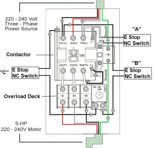
Let's start off on the basics, a Motor Starter and what it does. To do that, consider a relay, any relay, such as what switches your headlights on. Then consider that you have 3 separate contacts for your 3 phases. Now make the contacts very large, from the size of a dime to the size of a silver dollar. That relay just became a "Contactor". It's still a relay, just a very big one.

Now, the motor. . . A separate subject in and of itself, the reason it comes into the conversation is because most motors draw enormous current when starting. Depending on the motor and the load it is driving, that current may be 500-600%. That's 5 or 6 times the run current. Enough to melt fuses and cause the wires to rattle in the conduit. That current only lasts a few seconds, being a long time in motor circuits, but only a blip in people time. Fuses and circuit breakers aren't set up to handle that sort of current. Enter the "Overload Deck". . .

The overload deck, I don't know the proper name, that's what it's called in the field, is just a specialized circuit breaker designed to handle motors and their current demands. There are many different types but most use a "eutectic" metal, one that changes from solid to liquid at a very specific temperature. These are called "solder pots" in the business. When current passes through the solid solder, it generates heat. Low current, low heat; large current, large heat. The amount of heat, determined by the amount of current, applied over a specified time will cause the solder to go euctic. How fast is a function of how much current. When the metal melts, a latch is released which causes a contact to open.

Now combine the Contactor and an Overload Deck on the same pan and you have a Starter. The code calls for yada, yada, yada. . . The code is a required minimum for paid installers. The "code" is put out by the National Fire Protection Agency, and updated every three or four years. Why the code comes into play should be obvious by the issuing agancy. It keeps your shop from burning down, ruining the machines, and making the spouse angry. Should you inadvertantly violate the code and have a fire, your insurance can claim an "out" and you receive nothing but a heartache. So, follow the code where you can, it pays. .

Looking at your circuit overall, you will have a 240 volt, single phase circuit feeding your shop. It will have fuses(2) or a circuit breaker (CB) in the panel protecting the wires. Not the load, just the wires. . . In your shop, there may be a subpanel to isolate the different circuits. Including a "Rotary Phase Converter". The RPC should have a starter, after all it's just a motor and a few capacitors. (and maybe a kicker motor, depenting on who built it) The output of the RPC then feeds another, 3 phase, panel if you have more than one 3 phase load. From there, you feed the lathe, which may well be a system in and of itself. For a large, as in a repurposed industrial machine, there will be the main disconnect. That may or may not consist of a contactor and control circuits. It may well be just a (very large) switch. From there, you will have the motor circuit, including a starter and various controls.

What you are asking after is implemented with a latching, normally closed control switch, fairly light, interupting either the incoming line (a contactor) or better still interrupting the starter. This is easily accomplished by wiring the switch in series with the coil of the starter. And you're done.

This entry is approaching the length of a small book. For this, I also apologize. Electricity is a deep subject, where you can study a lifetime and not learn it all. I'm living proof of that. . . Finding an electrician today is a challenge, many of the "electricians" licensed by the state are nothing more than "wire men". Do it right up front and it probably will pass inspection. The "code" will tell you what is right, you just need to understand the language. Hence my introduction above.

Bill Hudson​

.
 
Bi11Hudson,
Thanks for your detailed reply. I really appreciate it. In the attached drawing of a motor starter circuit, which would be the correct location for the E Stop switch? I am thinking "A". Also, should I have either fuses or circuit breakers between the RPC and the motor starter? If so, what amp size? This lathe has a 2 HP motor. Thinking 20 amp.
One more question please. If I install a motor starter do I connect it between the RPC and the rotary switch (don't think so) or between the rotary switch and the motor? If the later, do I use the rotary switch to control forward/reverse operation by swaping two leads on the input to the contactor?
 
Sir; I cannot find any attached drawing. We will have to walk through this with text. First question, am I to understand the motor is a two speed machine? In answer to your question, yes, there needs to be a starter between the motor and the RPC. To clarify, assuming a two speed motor, the way the motor is wound will determine how much current is involved. This then involves a separate overload deck for each possible configuration. Which then involves a separate contactor for each overload device.

But, for a small motor you describe as a two(2) HP, we don't need to get overly complex. A single contactor will suffice for the E-Stop function. A single overload deck will be useless, we will depend on the existing fusing there. Having the contactor close to the machine will be preferable. It even would be possible to have it between the motor and the reversing switch. But, the wiring for a two speed machine is somewhat complex, so it's best to leave that alone and install the contactor between the RPC and the machine. I'm getting wound up again, need to slow down to the non-electrical level again. Sorry. . .

The reason for locating the contactor close to the machine is to allow a future install of "dynamic braking", should you ever opt for that. Or any other control functions you may desire. The basic wiring for the contactor will revolve around a "three wire control" circuit. A START and a STOP push button. These are low current devices, connecting to the coil of the contactor. The START button will be a common push button, often green in modern usage. The STOP button will be the latching, "mushroom" head, normally closed device. Such are available from any electrical supplier. I offer a link through Allied simply because I am familiar with them. I point to 22mm panel mount devices. There are many sources, and many configurations for E-stop controls.
In any case, do not use "dime store" switches for serious machines. Be sure to use industrial grade devices.

Given time, I can develop a "ladder" diagram suitable to your situation. If you desire, please feel free to contact me through Email if you need that level of assistance.

.
 
Sorry Bill Forgot to attach. Here it is. Motor is single speed.
 

Attachments

  • Motor Starter.JPG
    Motor Starter.JPG
    103.8 KB · Views: 13
Your diagram looks like a redrawn manufacturers diagram. Using such a diagram requires some familiarity with the specific equipment, which I don't have. Even different models from the same manufacturer have different configurations. A ladder diagram is much easier to read. I will draw up a "generic" diagram and forward to you in a couple of days.

Somewhere is a "3 wire" control station, the Start and Stop buttons. Where that station connects to the coil is where you want the EStop button. In its' simplest form, replacing the Stop button with a latching button will provide for basic interruption. There are several places where controls can be located, especially if there are several EStops. Wiring is simple for multiples, they are simply "daisy chained", all in series. At the root though, trouble shooting can be difficult or worse. Planning would pay dividends in that.

It does help that the motor is single speed. I don't know how I got it set in my mind that you had a two speed motor. I am getting old(70) and more easily confused, I guess, That sounds good, anyway, even if it isn't right. Because the machine and the RPC are cord connected with plugs, they both are exempt from many aspects of the "code". Not all, and good workmanship does still matter. But many parts of the code do not apply to portable equipment.

I will forward a diagram of what I think will apply in your situation in a couple of days. Then we would have a "common ground" from which to talk.

.
 
Back
Top